Home › Field notes › Laptop Sleeve Inner Module: Protection Meets Modularity
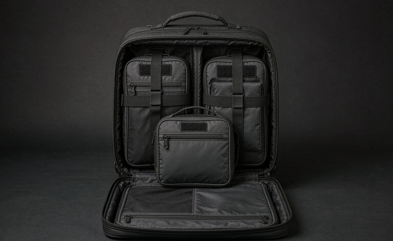
A laptop sleeve inner module has to reconcile two requirements that pull against each other. It must protect a rigid, fragile, expensive object, which argues for a close fit, dense padding and a stiff shell. It must also be a removable part of a modular system, which argues for a lighter build, a defined envelope and an interface the user can operate with one hand. Most products resolve this badly by choosing one side: either a thick, heavy sleeve that occupies half the chassis, or a light slip cover that protects nothing. This guide sets out the fit envelope, the padding decision, the corner treatment, what a drop test actually measures, and the specification lines that settle the argument before sampling.
Two Requirements That Pull Against Each Other
Protection and modularity optimise different things, and the tension is real rather than a matter of poor design. Understanding where each requirement bites is what makes the compromise defensible.
Protection wants mass, thickness and a close fit. A device is damaged by impact and by bending, and both are resisted by material that absorbs energy and by a shell that spreads a point load. Those properties come from padding volume and shell stiffness, both of which add weight and bulk.
Modularity wants a defined envelope and low mass. A module is lifted out, carried separately and re-inserted many times, so every gram and every millimetre of thickness is felt by the user on each cycle. A module that is difficult to remove stops being removed, at which point the modularity has delivered nothing but cost.
The resolution is to spend the protection budget where the device is actually vulnerable and save it everywhere else. Corners and edges take the impact; the middle of the panel does not. A module with substantial corner protection and a moderate face padding outperforms one with uniform thick padding, at lower weight - and it is the uniform-thickness approach that most products default to.
A third requirement is quieter and often forgotten: the module has to survive being a module. It will be lifted out, set on a desk, carried by a handle, dropped into a bag and slid across a surface. A protection design assessed only in its installed state ignores the exposure the sleeve receives while separated, which for a removable device module is a substantial share of its service life.
Selection rule: Evaluate a removable device sleeve in its installed position and again held separately, booking both during the 6-10 working day sampling window, because a sizeable share of its service life is spent outside the host chassis.
Fit Tolerance and the Device Envelope
Fit is the specification line most often stated badly. A sleeve described as fitting a nominal screen size is not specified at all, because devices of the same nominal size differ in all three dimensions and in corner radius.
The correct approach is to specify the internal envelope in three axes with a stated clearance band, and to state the device family the module is designed around rather than a screen diagonal. A band that is too tight makes insertion difficult and puts the device under constant compression; one that is too loose lets the device move, and movement is what defeats the padding.
| Specification line | Value to state | Symptom when omitted |
|---|---|---|
| Internal envelope | Three axes with a clearance band | Device will not insert, or rattles |
| Corner radius | The radius the sleeve is cut to | Corner padding bunches and lifts |
| Insertion direction | Which edge enters first | Closure catches on the device |
| Maximum device mass | Stated figure | Handle or anchor fails in service |
| Closure position | Measured from a stated datum | Closure sits over the device edge |
The corner radius row is the one usually missing, and it is why corner padding lifts on otherwise well-built modules. Padding cut to a square corner cannot sit against a radiused device corner without folding, and the fold becomes a hard spot precisely where protection matters most.
Maximum device mass matters more than it appears to. A module is carried by a handle or anchored in a chassis, and both are sized against an assumed load. Stating the mass converts an unbounded risk into a specified one and gives the inspector a rule to apply.
Verdict: State the internal dimension band rather than a nominal screen size, since devices sharing one nominal figure differ by enough to turn a correct fit into a loose one before any lot is drawn at AQL 2.5.
Padding: Thickness, Density and Recovery
Padding is specified by three properties, and softness is not one of them. Softness is a perception; the properties that determine protection are thickness, density and recovery.
Thickness sets how far a point load has to travel before it reaches the device. It is the most effective property per gram and the one that consumes the most envelope, which is why the thickness budget should be concentrated at the corners and edges rather than spread evenly.
Density sets how much energy a given thickness absorbs. Low-density foam bottoms out - it compresses fully under a modest load, after which additional thickness contributes nothing. High-density foam resists bottoming but transmits more of the load. The useful specification is a stated density range with a compression behaviour described, not a qualitative description of feel.
Recovery is the property most often ignored and the one that determines whether the module still protects in year two. Foam that does not recover stays compressed at the points that are loaded repeatedly, and a permanently compressed corner is a corner with no padding. Where the module is carried in a chassis daily, recovery should be tested over a cycling regime rather than assumed from a single compression. A sleeve that recovers slowly rather than not at all is the harder case to detect, because it measures correctly the day after a test and fails quietly over a season of use.
Laminated constructions deserve a note. Bonding foam to a shell improves handling and prevents the padding shifting inside the cover, but the adhesive is a layer that can fail with heat and flexing. Where a bonded construction is used, coating and bond behaviour is read under ASTM D751 and the bond should be included in the conditioning of any test.
Bottom line: Specify padding by thickness, density and recovery rather than by softness, and re-measure after the care regime users will actually apply, because a layer that relaxes narrows the stated clearance on every unit built in the 35-50 day production run.
Corner and Edge Treatment
Impact rarely arrives at the centre of a panel. It arrives at a corner, and it arrives at the corner because that is the geometry that reaches the ground first when a bag is set down or dropped.
Three constructions exist. A padded corner builds extra foam into the corner of the cover, which is light and effective for modest drops and limited by how much foam can be packed into a corner without distorting the panel. A moulded corner adds a rigid or semi-rigid shell element at the corner, which spreads the load much better and adds a part, a tooling decision and a thickness penalty at the point where the module is thickest already. A suspended corner builds the sleeve so the device corner sits in a void rather than against material, which is the most effective approach and the most difficult to manufacture consistently, because the void has to hold its shape through repeated insertion rather than only on the first cycle.
Edge treatment is the second half of the problem. A device bent across its own length is damaged as surely as one struck at a corner, and bending is resisted by a stiff element running along the edge rather than by padding. Where a module is carried in a soft chassis with no frame sheet, that stiffening edge is doing structural work and should be specified as such.
Accessories inside the sleeve matter here too. A pen, a cable or a hard-backed notebook placed in the same pocket as the device creates a point load against the panel, and a pointed object pressed against a screen by the weight of the bag is a common cause of damage that no drop test predicts.
The practical control is a dedicated cavity with a soft lining for anything hard, and an explicit instruction not to share the device pocket. Where a product ships with a warning of that kind, the warning is doing engineering work, and it is cheaper than the padding needed to make the warning unnecessary.
Drop Testing and What It Actually Measures
A drop test is a comparative instrument, and its value depends entirely on how the request is written. The table sets out the fields that make a result interpretable.
| Request field | Value to state | Ambiguity removed |
|---|---|---|
| Drop height and surface | Height, and the surface material | Concrete and board are not comparable |
| Orientation | Which corner or face strikes first | A favourable orientation is not a result |
| Test load | Device mass or a specified surrogate | An empty sleeve tests nothing |
| Repetition | Number of drops and whether per orientation | One drop is an anecdote |
| Endpoint | What counts as damage to the surrogate | Failure is defined before, not after |
The surrogate row is the one that makes or breaks the exercise. Testing with a real device is expensive and unrepeatable; testing with an unloaded sleeve is meaningless. A surrogate of the correct mass, with a damage indicator that can be inspected, gives a repeatable result at low cost.
Transit testing is a different instrument and should not be substituted. ISTA 3A describes a parcel-drop and vibration sequence for packaged goods, which tells a buyer how the product survives distribution. It says nothing about the user dropping the bag on pavement, and a result from one should never be presented as evidence for the other.
Where budget allows one test, choose the oriented corner drop on a stated surface over any general sequence. The corner drop is the event that happens in service, and a module that survives it will survive the milder events.
Takeaway: Choose an oriented corner drop onto a named surface over any general sequence, and record the orientation, surface and repetition count so the result stays comparable across the MOQ 500 order and every repeat batch.
Attachment Inside the Chassis
How the module is held inside the chassis determines whether the modularity is used. Three options exist and the choice is a use-frequency decision.
A loose slip fit is the simplest and the fastest to operate: the module drops into a dedicated cavity and lifts out. It requires the cavity to be dimensioned, and it requires the module to stay put when the bag is inverted, which usually means a closure or a friction fit rather than gravity.
An anchored fit attaches the module to the chassis by a fitting - hook-and-loop, a snap, or a magnetic-guided plate. It stays in place under any orientation and costs the user one extra operation each way. Where the device is removed from the bag frequently, that extra operation is felt every time.
A hybrid arrangement is often the right answer: the module is anchored lightly so it cannot fall out, and the anchor releases with a single motion. That requires a fitting with a defined release force, and the release force should be stated as a band rather than as a single value, because too stiff is as much a defect as too loose.
Position inside the chassis matters as much as the attachment. A device carried against the back panel sits close to the user's spine and is protected by the frame sheet; one carried in an outer cavity is exposed to direct impact. Placing the module against the back panel is the single cheapest protection decision available, and it costs nothing but layout discipline, provided the cavity is dimensioned so the device cannot press against a frame sheet edge or a harness attachment point on the inside face. The chassis layout rules are documented under the modular work backpack notes.
Judgement: Match the attachment method to how often the module is taken out, and route the pocket clear of the 25 mm attachment tape rows and harness anchors running along the chassis interior.
Secondary Loads: Cables, Adapters and Heat
A device module rarely carries only the device. Three secondary loads complicate the design and each has a specific response.
| Secondary load | Problem it creates | Build response |
|---|---|---|
| Power adapter and cables | Point load against the device panel | Separate pocket on the outer face |
| Heat from a running device | Trapped warmth, foam softening | Vent path; avoid sealing the module |
| Documents and notebooks | Bending load across the device | Rigid divider between the two zones |
| Hard accessories in the same pocket | Concentrated pressure on the screen | Dedicated slip with a soft lining |
Heat is the one most often overlooked, and it interacts with the padding decision. Foam properties are temperature-dependent, and a module that seals a warm device against a warm back panel operates the padding at a temperature it was never assessed at. Where a device is likely to be carried while running, a vent path is a performance feature rather than a comfort one.
Cables and adapters should be given their own pocket on the outer face of the module rather than sharing the device cavity. This is partly a point-load argument and partly a retrieval one: a user reaching for a cable should not be reaching past a fragile object.
Care and cleaning close the list. A module that cannot be wiped clean, or that distorts under the cleaning regime it will actually meet, fails commercially long before it fails structurally. Care and dimensional stability is read under ISO 6330, and the method should be named in the specification alongside the padding properties. A module that shrinks even slightly under the care regime it will actually meet tightens the clearance band and can convert a correct fit into one that is too tight after the first clean.
Specification Checklist for the Module
Eleven lines close the specification, and most of them are the subject of an earlier section. Stated together they form a document a pattern maker can work from without asking a question.
Internal envelope in three axes with a clearance band. Corner radius the sleeve is cut to. Insertion direction. Maximum device mass. Closure position measured from a stated datum. Padding thickness per zone, since corner and face will differ. Padding density with compression behaviour described. Recovery requirement after a stated cycling regime. Corner construction type. Attachment method with a release-force band. Care and dimensional stability method, named as ISO 6330.
Two lines are worth adding because they prevent later arguments. The first is the shell material with a coating adhesion figure under ASTM D751 where a bonded construction is used, because a delaminated sleeve is a cosmetic and functional failure at once. The second is the inspection treatment: sampling levels from ISO 2859-1 with AQL 2.5 agreed in writing, plus a fit check performed on every unit rather than on a sample, since a sleeve that does not fit is the one defect a user discovers immediately.
Sampling resolves all of it. A plain sleeve is built in 6-10 working days; specifying moulded corners or a bonded shell moves the round out to 12-15 working days. The fee of USD 50-150 per configuration is refundable against the order, which makes it the cheapest point at which to discover that a corner radius is wrong. Test the sample with the actual device rather than with a ruler: a sleeve that measures correctly can still fail on insertion if the closure sits where the device edge lands, and that is a defect no dimension on the drawing will reveal. Fit is a physical behaviour rather than a measurement, and the sample is the only place it can be observed before a run commits to it. For the module families that share this interface, see the everyday carry module range. A sleeve that fits the device but not the cavity has solved half the problem, so both envelopes belong on the same drawing.
Spec rule: Put the device envelope and the cavity envelope on one drawing with a stated mass limit, and hand that drawing to the sampler before the T/T 30/70 balance falls due, because a sleeve meeting one envelope and missing the other is rework.
Frequently asked questions
Why is a nominal screen size not a fit specification?
Because devices of the same nominal size differ in all three dimensions and in corner radius. Specify the internal envelope in three axes with a clearance band and name the device family rather than a screen diagonal.
How much clearance should a device sleeve have?
Enough to insert without forcing and little enough to prevent movement. Too tight makes insertion difficult and compresses the device; too loose lets it move, and movement defeats the padding.
Why does corner radius appear on a sleeve specification?
Padding cut to a square corner cannot sit against a radiused device corner without folding. The fold becomes a hard spot at exactly the point where protection matters most, and it is a common cause of corner padding lifting.
Should padding be uniform across the module?
No. Concentrate the thickness budget at corners and edges, where impact arrives, and keep face padding moderate. A zoned approach outperforms uniform padding at lower weight.
What padding properties should be specified?
Thickness per zone, density with compression behaviour described, and recovery after a stated cycling regime. Softness is a perception and not a specification; density without recovery ignores what happens in year two.
Why does foam recovery matter?
Foam that does not recover stays compressed at the points loaded repeatedly. A permanently compressed corner is a corner with no padding, which is why recovery should be tested over cycling rather than assumed from one compression.
What should a drop test request state?
Drop height and surface material, the orientation striking first, the test load as a surrogate of correct mass, the number of repetitions, and the endpoint that counts as damage. An unloaded sleeve tests nothing.
Is ISTA 3A the right test for a device module?
It is the right test for distribution, not for user drops. ISTA 3A describes a parcel-drop and vibration sequence for packaged goods and should never be presented as evidence of protection against a bag being dropped in service.
Which corner construction performs best?
A suspended corner, which leaves the device corner in a void, performs best and is the hardest to manufacture consistently. A moulded shell corner spreads load well and adds thickness; a padded corner is lightest and suited to modest drops.
How should the module be held inside the chassis?
Match the method to use frequency. A loose slip fit is fastest but needs a closure to stay put; an anchored fit is secure and adds an operation. A light anchor releasing in one motion is often the best compromise.
Where should the module sit inside the bag?
Against the back panel, close to the frame sheet. Placement is the cheapest protection decision available and costs only layout discipline; an outer cavity exposes the device to direct impact.
Why should cables and adapters have a separate pocket?
Two reasons: they create a point load against the device panel, and a user reaching for a cable should not be reaching past a fragile object. Put them on the outer face of the module.
Does heat from a running device affect the module?
Yes. Foam properties are temperature-dependent, and a module sealing a warm device against a warm back panel operates the padding outside its assessed range. A vent path is a performance feature, not a comfort one.
How long does sampling a device module take?
Six to ten working days covers a plain sleeve; 12-15 working days applies where moulded corners or a bonded shell are specified. The fee is USD 50-150 per configuration and comes back as a credit on the order.