Home › Travel Systems
Field-tested modular load carriage
Modular Travel Backpack: Convertible Travel Bag Specification Guide
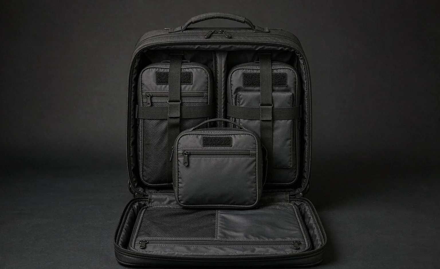
A modular travel backpack is a cabin-sized carrier whose shell, suspension and internal packing units are drawn as one controlled system, so a convertible travel bag can be stripped at a checkpoint, reassembled at the bench and stacked behind a roller without unpacking the contents. That definition is testable: the body has to pass a rigid gauge in its fully dressed configuration, not in the configuration that photographs well. Cabin rules differ by carrier, fare class and aircraft, so dimensions are handled here as a planning envelope drawn from published airline data and the IATA cabin-bag reference, re-verified per programme rather than promised. Exterior modules are the usual reason a compliant shell fails at the gate, because every pouch hung outward spends width the allowance never gives back. Programme planning starts at an MOQ of 500 pieces; prototype work occupies 6–10 working days and reaches 12–15 where the conversion mechanism is involved; bulk output closes in 35–50 days after approvals land; final inspection is set at AQL 2.5. The sections below move from dimensional budgeting through the module manifest, screening behaviour, roller integration, carry stability, theft exposure, laboratory routes and shipment terms.
Cabin Allowances as a Planning Envelope, Not a Promise
A cabin allowance is enforced by a rigid frame at the gate, and that frame has no tolerance. Anything protruding is measured as part of the body: a side pocket distended by a bottle, a pouch lashed to the front face, a harness hanging loose. The consequence for a modular programme is uncomfortable but simple. The dressed configuration is the product. A shell that measures correctly when empty and fails once its approved unit kit is fitted is not a cabin bag, whatever the specification sheet claims. Buyers should therefore require dressed dimensions to be stated with the module set installed, taken at the widest point, and recorded together with the gauge type used.
Published limits differ by carrier, by fare class and by aircraft type, and they change without notice. The IATA cabin-bag reference of 56 × 45 × 25 cm is a useful planning anchor because many full-service carriers publish something close to it, but it is a reference rather than a rule and no carrier is obliged to honour it. Several North American operators quote nearer 56 × 36 × 23 cm, a materially thinner depth and the most common reason a body drawn for a European band fails on a domestic rotation. Under-seat personal-item allowances cluster around 40 × 30 × 15 cm, which caps any companion unit intended to travel with the main body. Cabin weight caps commonly sit between 7 kg and 10 kg, with lower ceilings on regional aircraft and on some regional operators elsewhere. Every value has to be re-checked against the routes a programme actually sells into; the figures here are planning inputs, not commitments.
Gate checking is the case most specifications ignore. On a full flight, or on a regional aircraft with a smaller bin, a compliant cabin bag is taken at the aircraft door and loaded into the hold, where it meets conveyor handling, stacking under heavier bags, wet or dirty surfaces, and a drag by a handle never designed for that duty. Treating the product as cabin-only and building it lightly is a decision that generates complaints from customers whose bag was checked on the third leg of an itinerary. A defensible travel specification designs for the checked case even when the marketing position is carry-on.
The document should name four things: the reference allowance the body is drawn against, the verification route per season, the dressed measurement method, and the compression behaviour. Compression deserves particular attention, because a body that only fits after a hard squeeze will not fit repeatedly; the check is to seat a packed, dressed sample into a rigid gauge ten times in succession and record the result each time. Programmes sharing one shell across audiences can align the dimensional budget with the shared modular backpack platform already in the range, so a single body serves cabin travel and general duty without two sets of patterns.
| Planning constraint | Typical published band | What it forces on the carrier | Verification action |
|---|---|---|---|
| Cabin bag linear envelope | IATA cabin-bag reference 56 × 45 × 25 cm; many full-service carriers publish close to it | Height and depth ceilings, with handles and protrusions counted | Measure the dressed sample in a rigid gauge |
| North American overhead | Commonly quoted near 56 × 36 × 23 cm | Thinner depth; flat exterior items only | Confirm with each carrier before artwork freeze |
| Under-seat personal item | Often near 40 × 30 × 15 cm | Caps the companion unit sold with the body | Fit trial at a representative seat pitch |
| Cabin weight cap | Commonly between 7 kg and 10 kg, lower on regional aircraft | Mass budget set before contents are added | Weigh the empty dressed body at first piece |
| Gate-check fallback | Applied when bins fill or a smaller aircraft is used | Base, handles and closures must survive hold handling | Design and test the checked case as well |
| Gauge tolerance | No published tolerance; agent judgement applies | Compression must be repeatable, not a one-off squeeze | Ten consecutive fits with a packed load |
| Dressed width | Exterior modules add to every dimension | A module placement policy on the mounting map | Measure with the approved unit set fitted |
| Expansion state | Expanded gusset exceeds the packed band | A compression return that restores the declared envelope | Gauge fit immediately after expansion cycling |
Conversion Architecture: What Changes and What Stays Fixed on a Convertible Travel Bag
A convertible travel bag earns the description when the change of configuration is engineered rather than improvised. Three axes exist. Carry-mode conversion moves the body between backpack, shoulder and hand carry, usually by stowing or swapping a harness. Capacity conversion changes the packed envelope through an expansion gusset or a compression return. Module conversion adds or removes packing units and exterior pouches. A product can occupy one, two or all three; what matters is that each one has a defined anchor set, a controlled hardware family and a written cycle expectation, because a conversion that depends on operator goodwill fails in service.
Across every configuration, three things must not move: the structural seams that carry packed mass, the harness anchor points, and the closure geometry that keeps contents inside. A hideaway harness that detaches from a cosmetic panel is the classic failure, because shoulder load then passes through a face layer instead of into the yoke. Where a body converts to shoulder carry, the single-point anchor needs the same backing treatment as a backpack harness root. Where capacity expands, the gusset needs a controlled return, or the body grows permanently and stops entering the gauge it was drawn for.
Conversion frequency belongs in the document as a number. A travel body used on a weekly shuttle reconfigures far more often than one used twice a year, and the failure modes scale with cycles: adjuster slip on webbing, hook-and-loop matting, slider wear at a stowage channel, and zipper tracking where a cover flap is pulled open repeatedly. Writing an expected cycle count with a defined end state — no slip beyond a stated distance, closures still engaging, no audible rattle — turns a vague durability claim into a testable clause. Ranges built on the same shell as a convertible carry architecture can carry the cycle evidence across channels rather than re-testing for each one.
The interface has to be frozen before artwork. Once a stowage channel, a harness anchor or a unit rail is committed, changing it reopens pattern, sample and validation work. The practical sequence is to agree the conversion set, draw the anchors, build a representative sample, run the cycle test, and only then release artwork and packaging. Buyers who reverse that order usually pay for a second sampling round, and a second round costs calendar time that no freight mode recovers. The dimensional budget and the unit manifest should be signed off at the same gate, since both constrain the pattern permanently.
| Mechanism | Configuration unlocked | Anchor that must stay constant | Cycle evidence required | Penalty accepted |
|---|---|---|---|---|
| Hideaway harness in a zip channel | Backpack to hand carry with a clean exterior | Yoke seam and the upper harness root | Channel zipper cycling with the harness packed inside | Bulk behind the back panel and possible pressure points |
| Detachable harness on paired buckles | Backpack to shoulder or hand carry | Upper harness root tied into the yoke and its backing | Repeated mating and unmating of the controlled hardware pair | Hardware noise and the risk of mismatched halves |
| Detachable single-strap sling mode | Backpack to cross-body carry for short walks | Lower opposite-side anchor and its reinforcement | Single-anchor load trial at the declared packed mass | Asymmetric loading pulls the body out of square |
| Expansion gusset with compression return | Capacity conversion of one packed band | Side seam and base seam at the gusset ends | Expand-and-return cycling followed by a gauge fit | Growth becomes permanent if the return is weak |
| Removable day unit clipped to the harness | Module conversion for excursions at destination | Clipping point and the structure behind it | Loaded swing trial with the declared contents | Added depth at the front plane |
| Compression-only volume control | No true conversion; packed bulge management | Compression strap run and its anchors | Repeat gauge fit after ten compression cycles | Adds no usable volume |
| Fixed shell with no conversion | Single-purpose cabin body | Standard harness root and closure geometry | Only the dressed gauge fit and the drop series | Narrower channel appeal |
Packing Units and the Module Manifest
Packing units turn one cavity into a set of addressed volumes. The benefit is not tidiness; it is that a wearer can reach a single class of contents without disturbing the rest, and that the same shell serves a three-day business trip and a two-week field rotation by swapping the unit set. A manifest should therefore be written before the shell is drawn, listing each unit by name, target volume, contents class, shell material, closure type, interface method and the check that accepts it. A unit described only as a cube arrives as whatever the sample room happened to have to hand.
Seven units cover most travel programmes. A garment compression cube in the 8–12 L band takes folded clothing and is the unit that makes compression meaningful, because compressing clothing inside a cube works while compressing a whole cavity does not. An electronics bay of 4–6 L holds a laptop, a tablet and their chargers, and it is the unit that decides checkpoint behaviour. A shoe cell of 6–8 L isolates dirty soles from clothing. A wet pocket of 2–3 L handles damp items and toiletries. A flat document sleeve carries passports, boarding passes and papers without folding them. A liquids pouch near 1 L matches the volume most cabin liquid rules allow per container set. A laundry sac closes the loop for the return leg. Volumes are programme targets rather than standards; what must be fixed is the footprint each unit occupies inside the shell, because that is what the pattern has to accept.
The liquids and wet units deserve material thought rather than marketing. A welded or high-frequency seam contains liquid where a sewn seam wicks through needle holes. A coated lining wipes clean where a brushed tricot retains odour. A closure that seals under pressure in a hold behaves differently from one that seals upright in a cabin. Position matters most: a liquids pouch buried under a cube stack forces the wearer to open the main cavity in a queue, which is exactly the behaviour checkpoint design punishes. Where the electronics bay is concerned, aligning it with laptop bay engineering keeps suspension, corner clearance and closure logic consistent across the range.
Interface choice decides whether units stay put or migrate. A loop field inside the shell gives continuous placement and quiet handling, but it mats with lint and loses grip where a loaded unit creates a peel edge. A slot board or rail gives repeatable placement and a positive stop, at the cost of fixed positions and more tooling. Elastic retainers are cheap and forgiving but lose tension with heat and age. Whichever route is chosen, the kitting plan has to be explicit: how many units ship inside the body, which are sold as spares, how replacements are matched by revision, and how the retail pack lists them. Short or mismatched kits are one of the most common causes of a rejected shipment, and they are invisible to a standard bag checklist.
| Unit | Target volume band | Construction requirement | Interface method | Acceptance check |
|---|---|---|---|---|
| Garment compression cube | 8–12 L | Compression zipper with a controlled return and a pull that survives repeated use | Loose fit in the main cavity, retained by the shell walls | Compress and release ten times; confirm the cube returns to its stated footprint |
| Electronics bay | 4–6 L | Suspended sleeve, corner clearance and a padded divider | Rail or slot board against the back panel | Lay-flat opening trial with the largest declared device |
| Shoe cell | 6–8 L | Wipe-clean coated lining and a seam that does not wick | Base-of-shell position or a removable cradle | Fit trial with the largest shoe size in scope |
| Wet pocket | 2–3 L | Welded or sealed seams and a closure that holds under pressure | Interior position clear of the main zipper corridor | Fill, invert and hold; inspect for seepage at the seams |
| Document sleeve | Flat, no volume target | Stiff interlayer so papers do not fold | Flat pocket against the back panel | Insert a full document set and confirm the shell stays flat |
| Liquids pouch | Around 1 L | Transparent or semi-transparent face for inspection | Exterior-access position clear of the cube stack | Remove and replace without opening the main cavity |
| Laundry sac | 6–10 L | Light shell with a drawcord or roll closure | Stowed flat until the return leg | Confirm it consumes no footprint when empty |
| Cable organiser | Flat | Elastic loops sized to the actual plug population | Loop field inside the electronics bay | Remove and return each item without disturbing the rest |
Security Screening: Detachability, Tray Throughput and Reassembly
A checkpoint is a timed operation performed in a constrained space by a person who is not thinking about your product. Trays are limited, the bench after the scanner is small, and the people behind the wearer are impatient. A body that forces a wearer to unpack cubes in order to produce a laptop generates the worst outcome available: contents spread across a bench, a repack performed under pressure, and a unit left behind. The design target is therefore throughput, expressed as the number of trays required and the time to restore the body to its dressed state.
Three items drive tray count: large electronics, liquids, and metal mass. Large electronics are the one most programmes can engineer away, by giving the electronics bay an opening that lays flat against the back panel so a laptop leaves the body in one motion without disturbing clothing cubes. Liquids need an exterior-access pocket a wearer can lift out one-handed. Metal mass is subtler: a body bristling with buckles, carabiners, eyelets and stiff hardware triggers secondary screening more often than a quiet shell, so hardware selection is a screening decision as much as a strength decision. Reducing exposed metal is cheap at the design stage and impossible afterwards.
Reassembly is where quality shows. Units must return to addressed positions rather than to wherever they happen to fit after a rushed repack. That argues for a bay geometry with a positive stop per unit instead of a single cavity into which everything is dropped. It also argues for durable coding — colour, label or shape — that survives a year of use, and for a compression return that does not require two hands and a knee. Programmes serving frequent regional travel can borrow the discipline applied in screening-friendly everyday organisation, which keeps tray count down on the short-haul legs where time pressure is highest.
Verification is a drill rather than an opinion. Dress the body with the approved unit kit and the declared contents, walk it through a simulated checkpoint, and record: trays required, time to present electronics, time to present liquids, whether any other unit had to come out, whether the body closed afterwards with every unit in its addressed position, and whether any closure or adjuster had to be re-worked. Run the drill with more than one operator, because hand size and reach change the result. Repeat it after a wetting cycle or a laundering cycle, since a stiffened shell or a swollen liner changes access times noticeably.
| Event | Wearer action forced | Design response | Evidence to capture |
|---|---|---|---|
| Large electronics screening | Remove a laptop or tablet into a separate tray | Back-panel bay with a lay-flat opening and no cube stacked in front | Time from opening the body to presenting the device |
| Liquids inspection | Produce the liquids pouch | Exterior-access pocket with a grab handle clear of the main cavity | One-handed removal and return trial |
| Body through the X-ray | Place the dressed body into a tray | Dressed envelope that suits a standard tray footprint | Tray count and whether the body must be tilted |
| Metal detection trigger | Secondary screening or a pat-down | Reduced exposed metal, damped hardware, covered buckles | Trigger frequency recorded across repeated drills |
| Bench reassembly | Return every unit under time pressure | Positive stop per unit with durable coding | Units returned to addressed positions; count of errors |
| Overhead bin loading | Lift and stow the dressed body above shoulder height | Grab handles placed at the balance point and rated for packed mass | Lift trial into a representative bin height |
| Wet or damaged unit handling | Isolate a leaking item | Sealed wet pocket that contains failure locally | Inversion and hold test on the filled unit |
| Document access at the desk | Find a passport without unpacking | Flat rear-panel sleeve with a coded pull | Retrieval time with the body worn |
Travelling with a Roller: Pass-Through Sleeve, Strap Stowage and Stack Stability
Most long itineraries involve a roller at some point, even when the traveller buys a backpack. The practical requirement is that the backpack can ride on the roller handle instead of being worn while a case is also being dragged. That is a pass-through sleeve, and its engineering sits almost entirely at the mouth. The mouth takes the whole weight of the packed body whenever the assembly is lifted or tipped, so it needs reinforcement that continues into structural seams rather than a bar tack into a single face layer. Its width has to suit the handle geometry it will meet, which varies between cases; a sleeve cut for a narrow handle will not accept a wide one.
Strap stowage is the second half of roller integration. A harness left hanging catches on escalator steps, conveyor edges, aircraft armrests and crowded turnstiles, and it is the most commonly reported source of damage after a checked leg. Three routes exist. A zip channel behind the back panel is cleanest in use but adds bulk behind the panel and can create pressure points against the back. A detachable harness is lightest and cheapest, but the halves must be controlled as a pair and wearers lose them. A cover flap protects the harness without removing it, at the cost of another zipper and another failure point.
Stack stability is the part specifications usually omit. When a backpack rides on a roller handle, the combined centre of mass rises and moves rearward; a heavy body on a short-wheelbase case tips backward when the traveller stops suddenly. The document should therefore state the packed mass the sleeve was validated for, the handle height range the assembly was checked against, and the tip behaviour with the body loaded to its declared contents. A short stack trial — push, stop, turn, cross a threshold, ride an escalator — exposes the weakness quickly and costs nothing.
An integrated wheeled chassis, where the travel body carries its own wheels and telescoping handle, solves the roller question and creates several others: mass, wheel and handle failure modes, a stiff back panel, wasted volume in cabin mode, and a repair path most service networks do not hold. It suits checked-luggage programmes and ground-crew duty far better than cabin programmes. For most cabin-led ranges the better answer is a sleeve plus a stowable harness, which keeps the body light, keeps the back panel soft, and lets the traveller choose the roller independently of the pack.
| Option | What it does well | What it costs | Stack behaviour | Inspection focus |
|---|---|---|---|---|
| Pass-through sleeve with a reinforced mouth | Carries the body on a roller handle without wearing it | An extra panel layer and some back-panel volume | Stable while the handle height suits the case; tips backward when overloaded | Mouth reinforcement continuing into structural seams |
| Zip channel harness stowage | Clean exterior with nothing hanging | Bulk behind the back panel and possible pressure points | Best of the three, because nothing can snag | Channel zipper tracking after repeated cycling |
| Detachable harness | Lightest build and the softest back panel | Paired halves must be controlled; wearers mislay them | Good, provided the harness is stowed inside the body | Hardware mating and retention after repeated cycles |
| Cover flap over the harness | Protects the harness without removing it | Another zipper and another failure point | Acceptable, though the flap itself can catch | Flap closure durability and noise when worn |
| Integrated wheeled chassis | Self-contained rolling with no second bag | Mass, stiff panel, wheel and handle failures, repair burden | Stable by design but heavy to lift into a bin | Wheel attachment, handle extension and drop behaviour |
| No roller interface at all | Lightest and simplest construction | The traveller must carry the body or add a strap | Not applicable | Strap stowage still required to prevent snagging |
| Add-on trolley frame | Converts an existing body without redesign | Poor fit tolerance and a loose assembly in use | Unstable at speed and over thresholds | Frame retention and the wear it causes on the base |
Long-Haul Carry Stability and the Over-Width Risk of Exterior Modules
Travel loads are lighter than expedition loads and carried for longer in a worse environment: hot terminals, hard floors, stairs, crowds, and an expectation that the wearer still looks presentable at the far end. Comfort therefore comes from fit and stability rather than from maximum padding. A travel body in the 30–45 L band needs a harness with a defined yoke, load lifters that genuinely change the angle of the shoulder strap, a sternum strap that can be set, and a hip belt capable of transferring a real share of the mass rather than a decorative webbing strip. Torso adjustment matters because a travel range is sold across a wider population than a specialist outdoor range.
Exterior modules are where comfort and cabin compliance collide. Every pouch mounted outward adds depth at the widest point, and depth is the dimension most cabin gauges restrict hardest. The effect is not only dimensional: mass hung away from the back plane increases the moment acting on the shoulders, so a two-kilogram module on the front face feels heavier than the same mass packed against the back panel. A projecting pouch also catches on bin lips, turnstiles, aircraft armrests and door frames, and a snag at walking speed can rotate the whole body off a shoulder.
That is why a woven attachment field is usually the wrong answer on a travel shell. The geometry itself is familiar — rows cut from 25 mm webbing, spaced 38 mm apart vertically, with sewn islands every 50 mm along each row — and it is the correct answer where pouches must be repositioned and held under load. On a cabin body the same field spends width, snags, and advertises the contents. The better pattern moves organisation inside: a slot board or loop field behind a plain face, with a small covered area of rows for the rare exterior item. Programmes that do want external mounting should plan it with the rigour applied in PALS attachment geometry, including a declared usable row count and a mass class per zone.
Placement policy completes the picture. Dense items belong low and close to the back panel; flat compressible items can sit against the front face; side positions should be loaded in balance, because an unbalanced body pulls the wearer sideways on every step. A travel specification should state a maximum mounted depth for any exterior item and a mass ceiling for each zone, then verify by measuring the dressed body at its widest point and by walking a loaded wearer through a doorway, a turnstile and a representative bin. Long-haul comfort is ultimately a stability question: if the load does not move, the wearer stops noticing it.
| Mounting choice | Added depth at the widest point | Payload class | Risk at the bin or gauge | Policy recommendation |
|---|---|---|---|---|
| Woven rows on the front face | Full depth of the mounted pouch | Dense small items only | Snagging and gauge failure | Move inside; keep a covered area for rare exterior use |
| Side compression pockets | Depth along the narrow dimension | Flat or compressible items | Catches on bin lips and armrests | Keep shallow and balanced left to right |
| Bottom lashing straps | Minimal when not in use | Bulky soft items | Drag and abrasion against the ground | Accept with a protected base panel |
| Shoulder strap daisy chain | Negligible | Clips and light cords | Strap noise and catch points | Use soft hardware and manage the tails |
| Interior slot board | None on the exterior | Full range of units | No dimensional penalty | Preferred for cabin programmes |
| Covered front panel with hidden rows | None until opened | Full range of units | Slower access while the body is worn | Preferred compromise for mixed ranges |
| Detachable front pouch worn separately | None while stowed | Dense small items | Adds a second item to track | Accept where the pouch is sold separately |
| Exterior bottle pocket | Local bulge at the side seam | One rigid container | Distorts the dressed silhouette | Keep collapsible or move inside |
Theft Exposure and Visual Signature in Transit
Transit theft is mostly opportunistic and mostly fast. The realistic scenarios are an unzipped pocket in a crowd, a bag taken from a seat or a luggage trolley while the owner is distracted, a slash-and-grab on a crowded train, and whole-bag theft at a check-in queue or a left-luggage counter. Each has a different countermeasure, and none of them is defeated by a marketing word. A specification should name the scenario, name the countermeasure, and state plainly what the countermeasure does not do, because overclaiming is the real compliance risk here rather than the engineering.
Lockable sliders and a cable loop provide deterrence: they slow an opportunistic opening and let a wearer anchor the body to a fixed object. A lock is only as good as the slider it engages, so the slider has to sit inside the controlled hardware set rather than being sourced per order. A high-tenacity lining panel reduces the yield of a slash attack, at a genuine cost in mass, stiffness and hand feel; it belongs in the panel that faces a crowd rather than across the whole body. Rear-panel access to a document pocket keeps valuables behind the wearer, which remains the most effective low-cost measure available.
Contactless-card shielding is the claim most often overstated. A shielding layer addresses unauthorised reading of contactless cards while they remain inside the pocket, and it can be checked by a simple read attempt at a stated distance. It does not prevent theft, does not protect a card once the bag is gone, and is not a security certification of any kind. Copy should say what was tested and stop there. Visual signature is the other half of the problem: bright hardware, large external marks and an expensive silhouette attract attention in exactly the places where attention is unwanted. A low-visibility option — muted hardware, minimal external branding, a plain face — is cheap to offer and often sells well to the business traveller who is tired of being targeted.
What belongs in a buyer's document is a claim register: for every marketing statement, the mechanism, the test or inspection that supports it, and the qualification that must appear on the packaging or the product page. That register is what keeps a range out of trouble with a retail compliance team, and it is far easier to build before launch than to retrofit after a challenge. Theft-resistance language should always be written as deterrence and delay, never as prevention, and any lock or cable supplied with the body should carry its own instruction sheet so the wearer understands the limit.
| Scenario | Countermeasure | What it actually does | Cost to the build | Claim boundary |
|---|---|---|---|---|
| Unzipped pocket in a crowd | Lockable sliders and a rear-facing pocket | Slows an opportunistic opening | Low, once the slider is controlled hardware | Deterrence only, never a prevention claim |
| Bag taken from a seat or trolley | Cable loop anchored to a fixed object | Prevents a grab-and-run while anchored | Low; adds a loop and an instruction sheet | Requires the wearer to use it |
| Slash-and-grab on crowded transport | High-tenacity lining panel facing the crowd | Reduces the yield of a single slash | Mass, stiffness and hand feel | Does not make the body slash-proof |
| Whole-bag theft at check-in | Low visual signature and disciplined tagging | Reduces targeting | Minimal if planned at artwork stage | No device prevents removal |
| Contactless card reading | Shielding layer in the card pocket | Blocks a read attempt at the tested distance | Thin layer, negligible mass | State the test distance; imply no certification |
| Pickpocketing in a queue | Rear-panel document pocket | Keeps valuables behind the wearer | Low | Comfort and access must still be verified |
| Contents left at a checkpoint bench | Addressed unit positions with durable coding | Reduces items abandoned after a rushed repack | Negligible | Operational, not a security device |
| Bag opened in a hotel lobby | Covered closure and damped hardware | Removes the audible and visual cue | Low | Describe as discretion, not security |
Laboratory Routes and Inspection Evidence for Travel Builds
Material evidence comes first and should name the exact substrate. ASTM D5034 is the grab tensile route applied to face and lining cloth. ASTM D3884 and ISO 12947 provide abrasion routes by rotary platform and by Martindale respectively, and the coated laminate actually used has to be the specimen, because a coating changes both results. AATCC 127 covers resistance to water passage under a hydrostatic head, and ASTM D751 covers methods relevant to coated and laminated panels. None of them describes a completed article: stitch lines, needle perforations, zipper tracks and every opening decide what actually gets wet, so a complete-body wet review has to follow the fabric result rather than stand in for it.
Hardware and assembly need separate routes. ASTM B117 gives a controlled salt fog exposure that ranks finishes against one another on sliders, eyelets and plated parts; it is a ranking exercise rather than a forecast, and the meaningful step afterwards is a functional check rather than a rust grade. Zipper cycling on the main cavity and on any stowage channel predicts tracking failures that no fabric test will see. A dressed drop in the packed configuration, a pull on the pass-through sleeve mouth and on every grab handle, and a gauge fit repeated ten times cover the events a travel body genuinely meets. Where units ship as separate retail items, ISTA 3A informs parcel distribution testing.
Inspection evidence sits alongside the laboratory work. ISO 2859-1 supplies the statistical basis for the AQL 2.5 acceptance level used at final inspection. A travel defect library is needed, because an ordinary bag checklist never catches the problems that decide this category: sleeve mouth reinforcement missing, harness anchors landing in a cosmetic panel, a unit kit short or mismatched by revision, wet-pocket seams seeping, a stowage-channel zipper mis-tracking, and shade mismatch between the shell and its units. First-piece photographs, patrol records from the line and a retained reference sample carry the evidence that a closing inspection simply cannot see.
Market-access documentation has to match the real bill of materials. REACH (EC 1907/2006) governs substance declarations for the European destination. California Prop 65 drives warning language where exposure pathways apply. CPSIA comes into play where the intended user brings it within applicable limits. OEKO-TEX Standard 100 supplies useful textile and component evidence inside its certified scope. These are destination-scoped records rather than product certifications, and they must be rebuilt whenever a substrate, coating, colour or hardware finish moves. Change control should treat those items as controlled, with a re-check trigger attached to each one.
| Risk | Method reference | What the report covers | Blind spot | Programme follow-up |
|---|---|---|---|---|
| Face and lining tension | ASTM D5034 | How the nominated face and lining cloth behaves in tension | Says nothing about seam efficiency or stitch pull | Add an assembly pull on the completed article |
| Surface wear | ASTM D3884, ISO 12947 | Abrasion resistance of the coated laminate actually used | Flat coupon ignores seam stacks and folded edges | Approve by colourway, not by fabric family |
| Liquid entry | AATCC 127, ASTM D751 | Hydrostatic behaviour and coated-panel methods | No stitch lines, perforations or openings in the specimen | Add a complete-article wet review afterwards |
| Finish ranking on hardware | ASTM B117 | Relative corrosion ranking of finishes under fog | Ranks finishes; no prediction of service years | Operate every slider and buckle after exposure |
| Closure life | Project cycling method | Slider and channel behaviour over repeated use | No universal published number exists | Write a cycle count and an end state into the spec |
| Dressed drop and handling | Project method on a finished body | Packed behaviour at handle, sleeve and base | Orientation-dependent, so it must be defined | State the drop orientation and packed contents |
| Parcel distribution | ISTA 3A | Behaviour of a unit shipped as a retail pack | Built for parcel systems, not baggage handling | Use where units travel separately |
| Acceptance statistics | ISO 2859-1 | Statistical basis for the AQL 2.5 level | Cannot reveal hidden construction | Support it with first-piece photographs and patrol records |
Programme Terms, Logistics and Market-Access Records
A travel programme follows the gates used on any controlled build, plus two extra conditions: the dimensional budget must be locked before artwork, and the unit manifest must be locked before the shell pattern goes out. The sequence runs brief, interface definition, trim approval, sample, validation, pre-production reference, bulk output, inspection and shipment. Dropping the trim approval step is the usual reason for a second sampling round, because fabric, hardware and packing units tend to be swapped together for cost reasons and then act differently as a group.
MOQ 500 applies to every travel configuration, and a range normally splits that across colourways rather than styles, because a second style means a second pattern and a second validation. Prototype work occupies 6–10 working days; complex conversion mechanisms or unit interfaces push that to 12–15. Mass production occupies 35–50 days once approvals and inputs are closed. Payment runs T/T 30/70 while the shipment basis stays FOB Xiamen. Every number quoted while a sample is still under review stays indicative, tied to FOB Xiamen terms at a 500-unit floor, because fabric selection, hardware family, unit kit content and test scope all shift it.
Capacity planning rests on our SGS-verified production base, which carries 149 machines across 7 production lines, staffed by 137 people, on 4,950 m² of floor, with monthly throughput scheduled at 200,000 units. Our production team plans travel orders around fabric, hardware and unit-kit lead times, since the unit kit is usually the item that sets the critical path when a programme ships several cubes inside every body. Where a season needs more capacity than one site can hold, our vetted partner facilities can be brought in under the same interface documentation, provided the revision is frozen first and the approved reference sample travels with the order.
Shipment planning chooses between ocean transit occupying 25–35 days on planned volume, air freight taking 5–8 days where a launch date governs, and courier moving samples, spare units and small parts in 3–5 days. Packaging has to suit the channel: a polybag per body, cube kits counted and bagged as a set, a carton specification that survives stacking, and a barcode and label layout agreed before packing begins. Programmes ready to move from an agreed shell into a complete interface build can continue into custom modular backpack programmes once the dimensional budget, the unit manifest and the anchor set are signed off. REACH (EC 1907/2006), California Prop 65, CPSIA and OEKO-TEX Standard 100 records should be rebuilt per destination at the same gate, never after the goods are packed.
Frequently asked questions
What is a modular travel backpack in specification terms?
It is a cabin-sized carrier whose shell, harness and internal packing units are drawn as one controlled system. The shell declares a dimensional envelope, the harness declares fixed anchors, and every packing unit declares a footprint, a contents class and an interface method. It differs from a general-purpose pack in three measurable ways: dressed dimensions are published with the module kit fitted, the electronics bay is positioned for checkpoint removal, and exterior mounting is deliberately rationed because it spends cabin width.
Why does a cabin-legal shell fail at the gate once modules are fitted?
Because the gauge measures the dressed body, not the empty one. A shell drawn to a 56 × 45 × 25 cm planning envelope can lose its entire margin once a front pouch, a side pocket and a compressed cube stack are added, and depth is usually the first dimension to go. The remedy is a dressed measurement clause: state dimensions with the approved unit set fitted, taken at the widest point, and record the gauge type. Verify by seating a packed sample ten times in succession rather than once.
Should a programme design against the IATA cabin-bag reference?
It is a useful planning anchor but not a guarantee. The IATA cabin-bag reference of 56 × 45 × 25 cm matches or sits close to what many full-service carriers publish, yet several North American operators quote nearer 56 × 36 × 23 cm, which is materially thinner. Carriers also revise limits by fare class and aircraft type without notice. Design against the tightest band the programme sells into, re-verify per route each season, and publish dressed dimensions so the customer can judge.
How should dressed dimensions be written into a tech pack?
Name four things: the reference allowance the body is drawn against, the dressed measurement method including the module set fitted, the gauge or sizer type used, and the number of repeat fits required. Add a compression clause stating that the body must enter the gauge without a forced squeeze, plus a mass clause giving the empty dressed weight. Record all of it on the first-piece report so a repeat run can be compared against the construction that was actually approved.
What happens when a cabin bag is gate-checked?
On a full flight or a regional aircraft a compliant bag is taken at the aircraft door and loaded into the hold, where it meets conveyor handling, stacking and dirty surfaces. A body built lightly for cabin-only duty then generates complaints. The specification should cover the checked case as well: reinforced grab handles, a protected base, closures that stay shut under pressure, and a harness that cannot snag. Treat cabin compliance as a dimensional goal and hold survival as a separate requirement.
Which packing units belong in a travel module manifest?
Seven cover most programmes: a garment compression cube at 8–12 L, an electronics bay at 4–6 L, a shoe cell at 6–8 L, a wet pocket at 2–3 L, a flat document sleeve, a liquids pouch near 1 L, and a laundry sac at 6–10 L. Volumes are programme targets; the fixed items are the footprint each unit occupies, its closure type, its shell material and its interface method. Without a declared footprint the pattern cannot guarantee that the kit fits.
How should the liquids and wet pockets be specified?
Specify seam type, closure and position rather than volume alone. A welded or high-frequency seam contains liquid where a sewn seam wicks through needle holes. A coated lining wipes clean where a brushed tricot holds odour. A closure that seals under pressure in a hold behaves differently from one that seals upright in a cabin. Position matters most: the liquids pouch must lift out one-handed without opening the main cavity, or the wearer unpacks in a queue.
Where should the electronics bay sit for checkpoint handling?
Against the back panel, with an opening that lays flat and no clothing cube stacked in front of it. That placement lets a laptop or tablet leave the body in one motion and return to the same addressed position, which is what reduces tray count and bench errors. Corner clearance, a suspended floor and a padded divider should be stated as dimensions, and the bay checked with the largest device the programme declares support for.
How many packing units are too many?
More than a wearer can restore under time pressure. A practical limit comes from the reassembly drill: if a second operator cannot return every unit to its addressed position within the time a checkpoint bench allows, the manifest is too rich. Kitting cost and footprint set another ceiling, since each unit consumes shell volume and adds a spare-part line. Most programmes settle between five and seven units, with one sold separately as a spare.
What makes a travel body fast through security screening?
Low tray count and fast reassembly. That means a back-panel electronics bay that lays flat, an exterior-access liquids pocket, reduced exposed metal so secondary screening is less frequent, and addressed unit positions so contents come back correctly after a rushed repack. The evidence is a timed drill with a dressed, packed body: record trays required, time to present each item, and whether any unit beyond the required ones had to come out.
Can exterior attachment rows be used on a travel backpack?
Yes, but they should be rationed. Rows on a cabin body spend depth at the widest point, snag on bin lips and armrests, and move mass away from the back plane so the load feels heavier. The better pattern puts organisation behind a plain face, with a small covered area of rows for the occasional exterior item. Where rows are used, declare a usable count, a mass class per zone and a maximum mounted depth.
What do the 25 mm, 38 mm and 50 mm callouts govern?
The 25 mm figure is webbing width, setting the clearance a strap needs and limiting how far it can rotate once threaded. The 38 mm figure is the pitch between rows, governing how many rows one pouch height can reach and how much bearing surface the weave builds. The 50 mm figure is the spacing of the sewn islands that break each row, and those islands are what take the load. A tolerance band plus a backing stack belong with all three, or the field performs as decoration rather than structure.
How does a pass-through sleeve work with a roller?
A sleeve on the back panel slides over the telescoping handle so the backpack rides rather than being worn while a case is dragged. The engineering sits at the mouth, which takes the whole packed mass when the assembly is lifted or tipped, so its reinforcement must continue into structural seams. Width has to suit the handle geometry it will meet, and the specification should state the packed mass validated and the handle height range checked.
Should a travel backpack carry an integrated wheeled chassis?
Only where the programme is checked-luggage led or ground-crew led. An integrated chassis adds mass, a stiff back panel, wheel and handle failure modes and a repair path few service networks hold, while consuming volume in cabin mode. For cabin-led ranges a sleeve plus a stowable harness usually performs better: the body stays light, the panel stays soft, and the traveller chooses the roller. Where wheels are used, test wheel attachment and handle extension separately.
How is long-haul carry comfort specified without inventing claims?
Specify the mechanism and the test rather than the adjective: a yoke with a defined shape, load lifters that change strap angle, a sternum strap with a set range, and a hip belt that transfers a stated share of packed mass. Add a torso adjustment range and a fitted trial across the population the range sells to. Comfort language should be written as fit and stability statements backed by a wear trial, never as a performance guarantee.
What theft countermeasures are honest to claim?
Lockable sliders, a cable loop, a rear-panel document pocket, a high-tenacity lining panel facing the crowd and a shielding layer in the card pocket are all honest when described accurately. Each is deterrence or delay rather than prevention. Shielding copy should state the read distance tested and should imply no certification. A claim register linking every statement to its supporting test is the safest route through a retail compliance review.
Which laboratory routes apply to a travel build?
ASTM D5034 for grab tensile on face and lining, ASTM D3884 and ISO 12947 for abrasion, AATCC 127 for hydrostatic behaviour and ASTM D751 for coated panels, ASTM B117 for comparative hardware corrosion, and ISTA 3A where units ship as separate retail packs. ISO 2859-1 underpins the AQL 2.5 inspection level. Each of these qualifies a specimen or a parcel; the finished body still needs a dressed drop, a sleeve pull and a repeat gauge fit.
What are the commercial terms for a travel programme?
Each order starts at a floor of 500 pieces, normally split across colourways rather than styles. Prototype work occupies 6–10 working days and reaches 12–15 where the conversion mechanism or unit interface is complex, while bulk output is scheduled across 35–50 days once approvals and inputs are closed. Inspection is set at AQL 2.5, payment runs T/T 30/70, and the shipment basis stays FOB Xiamen. Prices quoted during sampling are indicative only, tied to FOB Xiamen terms at a 500-unit floor.
How long does delivery take once goods are ready?
Ocean transit occupies 25–35 days on planned volume, air freight takes 5–8 days where a launch date governs, and courier moves samples, spare units and small parts in 3–5 days. Packaging has to suit the channel: a polybag per body, cube kits counted and bagged as a set, a carton specification that survives stacking, and a barcode layout agreed before packing starts. Transit mode is usually chosen against the launch calendar rather than freight cost alone.