Home › Hiking Systems
Field-tested modular load carriage
Modular Hiking Backpack Engineering: Tactical Hiking Pack Load Design
A modular hiking backpack is specified by the route its packed mass takes to the wearer's skeleton, and a tactical hiking pack only earns the second word when that route survives the addition of external attachment modules. On a well-drawn trail shell the load leaves the compartment floor, passes into a semi-rigid back element, and lands across the iliac crest through a hip wrap shaped to sit there; the shoulder straps are left to stabilise the body and damp each footfall. Attach a heavy module to the outer face and the same shell behaves differently, because every increment of depth between the packed centre and the spine multiplies the torque the harness must resist. This page covers civilian trekking and trail product only. It covers load transfer and torso bands, the effect of external modules on the packed centre, capacity bands and module manifests, hydration routing and resupply reach, the gap between laboratory water data and a finished body in sustained rain, abrasion zoning, noise, and the validation and commercial framework behind an order. Nothing here describes weapon carriage, ammunition storage or ballistic protection, and no defence approval is claimed. Programme terms are fixed: an order floor of MOQ 500, prototype work in 6–10 working days, volume schedules of 35–50 days, and release inspection at AQL 2.5.
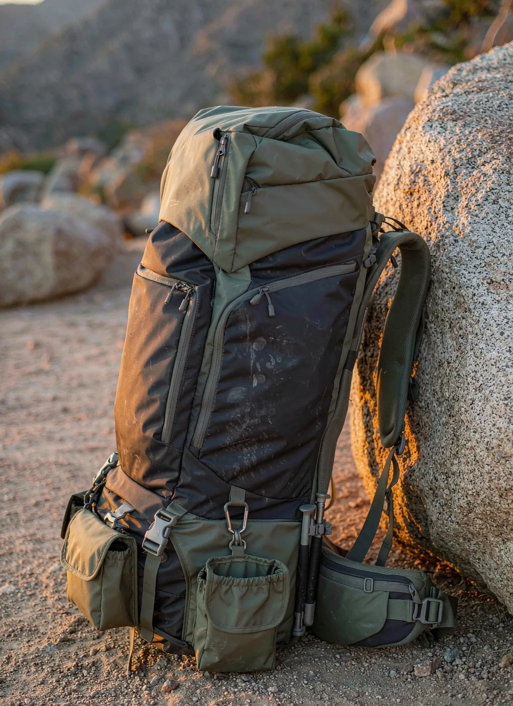
The Load Transfer Path: Compartment Floor, Back Element, Hip Wrap
A hiking body is a machine for moving weight, and every element in it either shortens or lengthens the distance between the packed mass and the wearer's skeleton. The chain begins where the contents rest. Dense items press on the compartment floor and against the rear wall; the floor and wall have to deliver that force into a semi-rigid back element rather than into foam; the back element carries it downward; and the hip wrap receives it across the iliac crest, where the pelvis accepts the greater share without complaint. The shoulder straps then work as stabilisers: they hold the body against the back, resist the rotation that pulls the load away from the spine, and damp the vertical acceleration that every footfall applies. Draw that chain on a marked sample and the weak link usually becomes obvious before any instrument is used, because the common failures are architectural rather than material: foam where a frame element belongs, a hip wrap that rides on the soft waist instead of the crest, or a strap anchor sewn into face fabric instead of into structure.
When the chain is broken the symptom is always the same, whatever the buyer calls it. The wearer reports a body that "rides heavy", numbness or tingling across the top of the shoulders, a trapezius that burns within an hour, and a hip wrap that migrates downward until it is doing nothing. Retailers see the consequence as returns and a review pattern that mentions discomfort rather than capacity. The engineering response is rarely a thicker pad. It is a shorter path: a back element stiff enough to hold the load plane, a hip wrap whose internal structure begins above the crest and wraps rather than belts, and a strap anchor that terminates in the same member the back element uses. Padding distributes pressure; it cannot create a route where none exists.
Load ordering inside the compartment is part of the same calculation, and it belongs in the user documentation rather than in folklore. Dense items belong close to the back plane and roughly between the shoulder blades, because that is where the moment arm is shortest. Light bulky items belong low and outward, where their volume costs the least torque. Nothing loose belongs at the very bottom, because a settling void there lets the whole packed mass slump and drags the centre away from the spine within the first hour of walking. Compression runs are structural tools in this scheme, not decorative webbing: pulling the sides inward shortens the effective depth of the packed block, stops the contents shifting on a side slope, and returns the body to the shape the harness was drawn for. On a modular shell the compression path must be reserved on the drawing, because a module threaded across the run disables the one control the wearer has over their own load.
Modularity interacts with all of this at the point where the attachment field meets the shell. Rows of 25 mm webbing laid at a 38 mm vertical spacing with a 50 mm horizontal repeat give a pouch a defined set of anchors, but the field itself is only as structural as the stack behind it. If the rows are sewn to a cosmetic face layer, pouch load goes into that layer and the whole panel dishes inward under a heavy module; if the stack behind the rows ties into the side seams, the base seam and the back element, the same module returns its load into the route described above. This is why the attachment drawing and the suspension drawing have to be released as one revision. Buyers who want the grid treated as a controlled subsystem rather than a styling feature can work from the same PALS attachment field geometry used across the rest of the range, so one pouch family serves several bodies without a second approval round.
Torso Bands, Harness Geometry and How a Size Run Is Planned
Torso length on a hiking body is measured from the seventh cervical vertebra down to the top of the iliac crest, and it does not correlate reliably with the wearer's height. Two buyers of identical stature can differ by a full harness band, which is why size runs are quoted in torso bands with a height range attached as guidance rather than as the controlling dimension. A harness that drops the hip wrap onto the soft waist instead of the crest transfers load into flesh, slips as soon as the wearer sweats, and produces the classic complaint that the belt will not stay put. A harness that is too short places the strap anchor above the shoulder line, so the load hangs from the top of the shoulders and the hip wrap never engages. Both outcomes are more damaging on a modular shell than on a soft day body, because the module set adds mass that the misfit then has to carry.
Adjustability is a compromise that has to be paid for in slip paths. A sliding yoke with a ladder adjuster lets one shell serve a wider band, but it introduces a joint that has to lock against a downward load and stay locked after repeated cycling; a hook-and-loop yoke is quiet and easily trimmed, yet it mattes with grit and loses position in wet conditions; a fixed harness has neither problem and simply fits fewer people. Where adjustability is specified, the acceptance trial must include a loaded walk with a re-measurement afterwards, because a yoke that creeps under load is worse than one that was set slightly wrong to begin with. The locking element, the webbing grade behind it and the retainer that stops the free tail flapping all have to appear on the component approval, not in a note to the sewing room.
Strap geometry carries more of the comfort result than the foam specification. The strap has to leave the body high enough to sit on the shoulder, curve around the neck without pressing on it, clear the brachial plexus at the outer edge, then wrap inward to meet the hip wrap at a point where the two systems share the load rather than fight for it. Width, foam density distribution and the split at the spine channel all belong in the drawing. A load-lifter strap is worth nothing if its anchor sits too low: the pull has to carry an upward component that rotates the top of the body toward the wearer, and an anchor placed horizontally simply drags the shoulders backward. The sternum strap does a different job again; it sets the distance between the two strap rails and stops them sliding outward on a steep descent, so its rail and its sliding range are specification items too.
Planning the size run is a commercial decision as much as an ergonomic one. Two or three torso bands cover most adult populations, but each band changes the hip wrap length, the strap length, the strap curve, the back panel length and the position of the sternum rail, which means a separate pattern nest and a separate set of first-piece checks. Programmes that attempt to cover the whole population with one adjustable yoke usually end up fitting nobody well and paying for it in returns. Programmes that run three bands share the shell, the attachment field and every module across the run, so the added cost sits in the harness rather than in the body, and the accessory list stays single. Where a range is being built for both trail and urban channels, the band structure should be decided before artwork, because a harness change later reopens the fit trial for every configuration.
| Fit variable | Misfit it produces when wrong | Where the wearer notices first | Trial that exposes it | Callout for the drawing |
|---|---|---|---|---|
| Torso band range | Hip wrap lands on the waist and slips under load | Belt migration and shoulder burning within an hour | Loaded walk with crest contact marked and photographed | Vertebra-to-crest range with the band boundary stated |
| Hip wrap angle and wrap direction | Belt presses instead of wrapping, so the crest receives nothing | Pressure at the front of the hips, no relief at the back | Loaded walk followed by a pressure mark review | Wrap angle, internal stiffener extent and closure position |
| Shoulder strap exit height | Anchor sits above the shoulder line and load hangs from the top | Numbness across the top of the shoulders | Static hold with the shoulder line marked on the sample | Exit height relative to the top of the back panel |
| Strap curve and neck clearance | Strap presses on the neck or the outer shoulder | Neck rub and outer-arm tingling | Wear trial with arm swing and head rotation | Curve template reference and outer edge radius |
| Load-lifter anchor position | Pull drags the shoulders backward instead of lifting the body | Body feels like it is falling away from the back | Incline walk with the lifter engaged and released | Anchor height and the rising angle of the strap run |
| Sternum rail and slider travel | Rails slide outward on a descent and the strap rolls | Strap rolling and collar-bone pressure | Descending trial on a graded surface | Rail length, slider travel and the stop at each end |
| Spine channel and padding split | Panel bridges the spine and concentrates pressure at one point | Hot spot over the spinal processes | Loaded walk with a pressure map or marked shirt | Channel width and the padding density either side |
| Adjuster locking behaviour | Yoke creeps downward as the walk continues | Harness that fit at the start and does not fit later | Loaded walk with position measured before and after | Locking element reference and the re-check interval |
External Modules and the Packed Centre: What the Moment Arm Does on a Hillside
The reason a modular hiking backpack needs more engineering discipline than a modular city body is torque. A module hanging on the outer face sits at a measurable distance from the back plane, and the harness has to resist that distance multiplied by the module's packed mass at every step. A light compressible item costs little and is barely noticed. A dense item in the same position changes how the body behaves: the wearer leans forward to compensate, the hip wrap works harder, the shoulders start doing the stabilising job they were never sized for, and the body that was comfortable for an hour becomes uncomfortable for a day. This is not a defect in the module or in the shell; it is the arithmetic of where the mass was placed, and it is decided on the drawing, not on the hill.
Position classes behave predictably and should be mapped before the range is launched. The outer front face is the worst place for anything dense, because it maximises the distance from the spine and exposes the module to snagging on rock, vegetation and doorways. Side columns produce a different problem: a heavy item on one side introduces an asymmetric component that shows up as sway on every footfall and as a persistent pull when the wearer traverses a slope. A lid-mounted cell raises the packed centre and makes the body feel tippy on loose ground, which matters more on scree than on a path. Base straps lower the centre, which is helpful, but they put the module where it meets rock, water and vegetation first. The general rule follows from the arithmetic: dense modules low and close to the spine, light bulky modules outward and high, and the upper outer face left clear as a matter of policy rather than preference.
Static reasoning understates the problem, because walking is a cyclic load case rather than a hold. Each footfall applies vertical acceleration, so the apparent load exceeds the static weight for part of every stride. A side-slope traverse adds a lateral component that works the outermost anchors and the side seams. Scrambling introduces rotation at whatever the module is hanging from and converts a tidy vertical pull into a prying action at the top anchor. Stream hopping and sudden stops add impulse. Any module position that survives a static check and fails one of those cases is a position that should have been excluded on the mounting map, and the cheapest way to find it is an instrumented or video-recorded walk on a slope with the full module set fitted rather than a bench pull.
The practical output of this analysis is a published mounting map with mass classes assigned to zones rather than a single statement of total attachment area. Each zone should name what may go there, what mass class it has been validated for, and what must never go there. Modules the wearer must reach while walking are the legitimate exception to the "keep it close" rule, and they are compensated for by keeping their contents genuinely light and by a compression run that holds them against the shell. Where a frequently used item is too dense to sit on the outer face at all, the better answer is to move it off the shell entirely and onto the harness; chest and waist access modules keep a water bottle, a phone or a snack inside the wearer's reach without lengthening the moment arm of the main body, which is why many trail ranges treat them as part of the system rather than as an accessory afterthought.
Capacity Bands and the Module Manifest for Day, Two-to-Three-Day and Multi-Day Use
Capacity figures cause more disputes between brands and their suppliers than almost any other line on a hiking tech pack, because the number depends entirely on the method used to produce it. A volume obtained by filling the body with a standard medium and measuring what went in, a volume calculated from the drawing, and a volume measured after the harness padding and the reservoir sleeve have taken their share are three different answers to the same question. The method belongs on the drawing next to the figure. So does the distinction between nominal and usable volume: the lid, the external pockets and the space occupied by a full reservoir are real volume in one sense and unavailable volume in another, and a buyer who plans a product around the nominal figure will discover the difference on the first packing trial.
The day band covers a body sized for a single outing with water, food, a shell layer, a small first-aid set and the electronics most walkers now carry. Usable volume here is dominated by access rather than by capacity: the wearer wants the water, the layer and the phone without unpacking, so the design effort goes into pocket placement, a lid or panel opening that works while the body is on, and a compression system that holds a half-empty body in shape. Modules in this band tend to be flat and few, and the attachment field is often reduced to a couple of rows plus a lash system, because every row adds mass and profile to a body that is meant to feel light.
The two-to-three-day band is where modularity earns its place. The wearer carries a sleep system or a bivouac shelter, more food, a cooking set, a larger first-aid and repair kit, and a change of clothing, and the load now has to be split into units that can be packed in a repeatable order and reached at a planned moment. This is the band where a written manifest pays for itself. Base straps or a lower compartment handle the sleep system; a wet cell or a lined pocket handles the shelter and anything damp; a dry cell handles electronics; a food cell keeps smell-bearing items together; and the lid carries the items that will be needed at the first stop rather than at the last. External modules in this band should still be light, because the shell is already deep and the moment arm is already long.
The multi-day band pushes the problem from capacity into structure. Additional volume without a corresponding increase in back element stiffness simply produces a body that sags away from the spine under its own contents, so the frame specification, the hip wrap structure and the base seam have to be re-specified rather than scaled. The module manifest grows to include a larger food cell, a separate cooking and fuel cell, a repair and spares cell, a water treatment set, and lash provision for a pad or poles. Access planning changes too: on a long walk the wearer plans the day around when they will open each unit, so the manifest should state retrieval frequency alongside position. Ranges that also sell into travel channels can share the manifest discipline used in travel-oriented module planning, where each unit is given a named content class before the shell pattern is cut.
| Module | Day band | Two-to-three-day band | Multi-day band | Preferred zone | Mass class | Retrieval while worn |
|---|---|---|---|---|---|---|
| Suspended reservoir sleeve | Standard fitment | Standard fitment | Standard, with a second water option | Against the back plane, upper third | Dense while full, collapses as it empties | Not retrieved; hose only |
| Filter-bottle side pocket | One angled pocket | Two pockets, one reachable one-handed | Two pockets plus a lid stash | Lower side, forward of the compression run | Dense | Every stop |
| Shell layer and wet cell | Front stash pocket | Lined front pocket with drainage | Separate lower wet compartment | Outer face, lower half | Bulky and light | At every weather change |
| Food and cooking cell | Single soft cell in the lid | Dedicated internal cell, smell-managed | Split food cell plus a separate cooking cell | Mid height, close to the back plane | Medium and dense | Planned stops only |
| First-aid and repair cell | Flat pouch in the lid | Marked external or lid cell | Two cells, one immediately accessible | Lid or upper outer face | Light | Unplanned, must be immediate |
| Sleep system straps | Not fitted | Base straps or a lower opening | Base straps with a removable divider | Lowest zone, outside the floor seam | Bulky and light | Once per day |
| Electronics dry cell | Lined top pocket | Sealed internal cell with a cable exit | Sealed cell with a power-bank sleeve | Upper zone, close to the back plane | Medium | Occasional |
| Trekking-pole and tool lash | Single side lash point | Lash pair with an upper capture | Lash pair plus a lower sleeve | Side, below the compression run | Light | Frequent on variable ground |
| Harness-mounted access pouch | Optional | Recommended for phone and snack | Recommended, often two | Hip wrap or strap rail, off the shell | Light | Continuous |
| Lid or top access cell | Standard | Removable, converts to a small carry unit | Removable with a documented load limit | Top of the body | Light only | Every stop |
Hydration Routing and Resupply Reach While the Body Stays On
Water is the single densest thing most walkers carry, which makes the reservoir the most consequential item in the whole load plan. Its correct position is against the back plane in the upper third of the body, suspended from a dedicated hanger rather than dropped into a pocket. That placement keeps a full reservoir inside the short moment arm where dense items belong, and the hanger matters because a reservoir that is merely placed will slump as it empties, taking the packed centre with it and folding into the bottom of the compartment. A full reservoir also occupies volume that other planning assumes is available, so the sleeve and its hanger have to be counted in the usable volume statement rather than treated as free space.
Hose routing is where most field complaints originate. A hose taken over the shoulder keeps the bite valve near the mouth but puts a bend at the top of the strap and leaves the tube exposed to cold; a hose taken under the arm shortens the exposed run and is easier to insulate, but it can catch on a strap adjuster and it presses against the chest on a steep climb. Whichever route is chosen, three details decide whether the system works: the exit port must clear the compression run so the tube is not crushed when the wearer pulls the sides in; the port must be sealed enough to keep rain out of the compartment while still passing the connector; and the bite valve needs a defined parking position, because an unparked valve drags on vegetation, picks up grit and ends up in the dirt at the first stumble. A shut-off at the reservoir end is worth specifying as standard, since it turns a leaking connector from a soaked load into an inconvenience.
Bottle-based systems take a different route to the same problem. A side pocket has to be angled and deep enough for a one-handed grab-and-return while the body stays on the shoulders, which is a geometric requirement rather than a preference: the pocket mouth needs to fall behind the wearer's hip, the elastic has to retain a partly filled bottle, and the pocket must not push the bottle into the compression run. Where a bottle cannot be reached one-handed, it will not be used, and the wearer will simply carry less water. Hip-mounted holsters solve the reach problem and keep the mass off the shell's moment arm, at the cost of a swing interference that has to be checked against the wearer's stride. The cell discipline developed for compact everyday carry module discipline transfers well here: give every water-carrying position a named capacity, a named reach method and a drainage path.
Resupply means more than water. A walker on a full day out needs a snack, a map or phone, sunglasses and a layer at unpredictable moments, and every one of those requirements is either designed in or paid for in stops. The planning target should be written down: the wearer can reach water, food, a layer and a navigation device without taking the body off. Hip-belt pouches and shoulder-strap pockets are the most direct route and cost almost nothing in moment arm because they sit on the harness; a front stash pocket handles a wet layer but adds depth; a lid pocket is quick to reach at the cost of raising the packed centre. Drainage deserves a line of its own, because bottle pockets and wet cells that hold water become grit traps and then abrasion sites, and a reservoir sleeve with no drain turns a slow leak into a soaked compartment.
| Option | Access while worn | Effect on the packed centre | Wet risk to other contents | Dominant failure | Specification note |
|---|---|---|---|---|---|
| Suspended reservoir with routed hose | Continuous, no hands needed at the valve | Improves it while full, then shifts as it empties | Connector or hose leak wets the whole compartment | Slumping sleeve and a crushed tube at the port | Hanger type, port position, drain and shut-off |
| Shoulder-strap soft flask | Fast, one-handed | Neutral to slightly forward | Low; isolated from the main volume | Pocket stretch and flask ejection on a descent | Pocket retention height and elastic recovery |
| Angled side bottle pocket | Fast when the geometry is right, useless when not | Adds a lateral component if unbalanced | Low, provided the pocket drains | Bottle lost on a scramble or unreachable one-handed | Mouth angle, depth and the compression clearance |
| Hip-wrap bottle holster | Continuous | Keeps dense mass off the shell entirely | Very low | Swing interference and belt rotation | Holster position relative to the stride |
| Front stash pocket for a layer | Fast, body stays on | Lengthens the moment arm when stuffed | Contains the damp item by design | Pocket tears at the lower corners | Corner reinforcement and drainage grommets |
| Lid pocket for small frequent items | Fast at a stop, awkward while walking | Raises the packed centre | Low if the closure is adequate | Contents crushed when the body is strapped down | Closure type and the compression interaction |
| Internal wet cell for damp gear | Planned stops only | Low and close, which helps | Isolates damp items from dry ones | Seam wicking at the cell corners | Liner construction and corner sealing method |
Rain Covers, Seams and Where AATCC 127 Data Stops Being Evidence
AATCC 127 reports the hydrostatic resistance of a flat textile: a specimen is clamped, a column of water is raised against it, and the result is recorded when penetration appears. That number is genuinely useful for ranking fabrics, for setting a coating specification and for catching a supplier who has quietly changed the finish. It is not evidence about a finished body, and treating it as such is the most common source of overclaiming in outdoor copy. The method sees no seam, no needle hole, no zipper assembly, no stitch line where the attachment field was sewn through the face, no hose port, no lid closure and no gap where a rain cover meets the body. A shell built from a textile with an excellent hydrostatic figure can still deliver a wet sleeping bag, because the water did not come through the fabric; it came through the construction.
Two further routes fill part of the gap. ASTM D751 addresses the behaviour of coated and laminated sheet material, including the adhesion and coating properties that decide whether a face textile keeps its resistance after folding, abrasion and storage in heat. ISO 6330 provides a domestic washing and drying route, and it matters here because a durable water-repellent finish is a finish: it declines with washing, with abrasion and with contamination, and a body that shed water on day one may wet out on the face after a season even though the coating behind it is intact. Any care statement printed on the product should match what the finished article actually survives, which is a reason to run the care route on a complete body rather than on a swatch.
The only test that answers the buyer's real question is a whole-article exposure. A rain-room or shower rig, with the body dressed, packed and wearing its full module set, reproduces the paths water actually takes: down the back panel, into the lid closure, along a zipper run, through a hose port, and into the seam at the base. Acceptance criteria have to be written before the exposure starts, because "no water inside" is not a criterion unless someone has decided where water is allowed to be, in what quantity, and after how long. A defensible statement names the exposure condition, the duration, the packed configuration and the acceptable outcome, and it is recorded against a sample reference so a repeat run can be compared with the original.
Rain covers remain the pragmatic answer for most trail ranges, and they should be specified rather than bundled. A cover solves the construction problem wholesale, because it does not care about seams or zippers; it also carries real costs. It has to be sized to the dressed body including its modules, which is why a cover cut to the empty shell does not fit once a sleep system is strapped on; it abrades at the contact points; it can pool water at the base and hold it against the body; it blocks access to every pocket it covers; it flaps and drums in wind; it is the most frequently lost item in the system; and a cover with no drain and no reflective mark is a service problem waiting to happen. The attachment point, the drain position, the elastic tension and the packed size all belong on the component approval.
What should reach retail copy is a statement the product can defend. Describe the construction honestly: a coated face textile with a stated hydrostatic figure, taped seams in named locations, a storm flap over the main closure, a cover supplied and sized for the dressed configuration. Avoid absolute exclusion language, because no assembled body with a zipper, a port and a seam stack can honour it, and the returns cost of the claim lands on the brand. Internally, the reliable strategy is layered: a coated face for the shower, taped or protected seams at the exposed paths, a liner or dry cell for the contents that must not get wet, and drainage wherever water can collect. Those four measures together outperform any single fabric figure, and they can each be verified on a finished sample.
| Route | Specimen tested | Question it answers | Question it cannot answer | Claim language it supports |
|---|---|---|---|---|
| AATCC 127 hydrostatic resistance | Flat fabric or coated panel | How the specified textile ranks against water under a head | Whether a sewn, zipped and ported body stays dry | A named fabric figure with the method stated |
| ASTM D751 coated sheet behaviour | Coated or laminated material | Whether the coating survives folding, adhesion stress and ageing | How the finished shell behaves at a seam stack | A coating specification with an ageing note |
| Whole-article shower exposure | Complete dressed body with modules | Where water actually enters a finished product | Field performance over a full season of use | A construction-level statement with conditions |
| Closure and port exposure | Zipper run, hose port, lid closure | Whether the specific path is protected | Anything about the rest of the body | "Storm flap over the main closure" and similar specifics |
| Seam tape peel and ageing review | Taped seam specimen, conditioned | Whether the tape bond holds after heat and flexing | Whether the tape was applied correctly in bulk | "Taped seams in named locations" with a care note |
| ISO 6330 care cycling | Finished body or large assembly | What the article survives in domestic washing | Industrial or field cleaning behaviour | Care instructions matched to the result |
| Field wear trial in sustained rain | Production samples in service | Whether the layered strategy works end to end | A repeatable laboratory comparison | None; it validates the design, not the copy |
Abrasion Zoning, Base Reinforcement and Contact Wear on Trail Shells
Wear on a hiking body is not distributed anything like evenly, and a shell specified with one face textile throughout is either overweight or under-protected. The map starts at the base. Every set-down puts the whole packed mass onto the lower front corner and the floor seam, on rock, gravel or a concrete station platform, and that single action accounts for more material loss over a season than the rest of the body combined. The lower side panels come next, because scrambling and squeezing past rock loads the sides in a way no city body experiences. The outer face takes brush, vegetation and the friction of a module shifting against it. The shoulder strap underside works against clothing and carries salt from sweat, which turns a soft abrasion into a cutting one. The hip wrap rubs at the hips and at whatever the wearer is wearing underneath. The back panel collects grit from a wet shirt. The lid takes transport, rope and the wearer's own handling.
The material response should follow that map rather than fashion. A higher-tenacity or heavier face textile at the base and lower front costs mass exactly where the wearer feels it least, since it sits below the packed centre and away from the harness. Coating the base improves water shedding and grit shedding at the cost of hydrolysis risk in hot humid storage and of a stiffer fold at the seam, so the coating decision is taken at material approval rather than at the colourway level. A bonded second layer gives a cleaner exterior than a sewn-on panel and removes a stitch line from the contact face, but it cannot be replaced in service; a sewn-on panel can be, and it puts a seam where the wearer can see it coming. Where the two meet, the seam should be placed high enough that it is not the thing sitting on the ground, and the corner radius should be generous, because a sharp corner concentrates every set-down onto a few square millimetres of stitching.
Structural reinforcement is a separate subject from the face textile. The base seam is a structural joint and should be built as one, with the floor panel carried up the front and side faces far enough that the packed mass bears on the joint rather than on a folded edge. Bar tacks belong at the compression strap anchors, at the root of every lash point and daisy run, at the base strap take-off, and at the corners of the attachment field, and each one has to land on a backing patch that ties into the shell rather than on a single face layer, because a tack driven through a single thickness punches a row of needle holes that becomes the tear path the reinforcement existed to stop. The compartment floor deserves particular attention: it carries the entire packed mass on every set-down, and a liner floor that floats over the base panel without being anchored to it is the first thing to fail on a heavy multi-day body.
Verification has to reproduce the dirty, wet version of the problem. ISO 12947 on the Martindale platform and ASTM D3884 on a rotary platform both give comparative surface-wear data, and both must be run on the coated construction actually used rather than on the greige fabric, because a coating changes the result completely. ASTM D5034 covers the grab tensile behaviour of the base textile and its backing. The conditions that actually kill a base, however, are wet abrasion and grit-contaminated abrasion, which are project methods rather than standard ones: rub the specified construction against a wet abrasive under a defined load and count cycles to a defined endpoint. Where hardware appears near the base or at lash points, ASTM B117 gives a comparative corrosion exposure; the result is only meaningful when the fitting is then operated and inspected rather than merely graded by eye.
| Contact zone | Mechanism | What fails first | Reinforcement response | Verification |
|---|---|---|---|---|
| Base and lower front corner | Repeated set-down under full packed mass on rock | Floor seam and the coating at the fold | Heavier base textile carried up the faces with a generous corner radius | Wet and grit abrasion cycling against the base panel |
| Lower side panels | Scrambling and rock contact on a traverse | Side seam and the base strap take-off | Backing patch behind the take-off, seam placed above the contact line | Loaded scramble simulation followed by seam inspection |
| Outer attachment face | Brush, vegetation and module movement | Row ends and the panel behind them | Backing stack tied into the side seams with tacked ends | Cycled module movement with magnified row inspection |
| Shoulder strap underside | Clothing friction loaded with sweat salt | Strap cover textile and the foam edge | Abrasion-resistant cover with a wicking inner face | ISO 12947 or ASTM D3884 on the strap cover construction |
| Hip wrap and lumbar panel | Rubbing at the hips against clothing | Wrap lining and its edge binding | Lining grade matched to duty, binding tucked out of contact | Wear trial with a lining review afterwards |
| Back panel and spine channel | Grit carried in on a wet shirt | Spacer mesh pilling and seam abrasion | Grit-shedding mesh with a drainable channel | Contaminated abrasion cycling on the panel construction |
| Compression strap anchors | Cyclic pull at a concentrated point | Anchor bar tack and the layer behind it | Tack onto a backing patch tied into structure | Cyclic pull followed by close seam inspection |
| Lash points and daisy roots | Oscillating load from a strapped tool | Loop distortion and the base reinforcement | Bound loops with a continuous backing run | Oscillating load trial with the tool fitted |
| Lid and top grab handle | Transport, rope and repeated handling | Handle webbing route into the shell | Webbing continued into a structural seam | Pull in the actual drag direction, not straight up |
Noise, Glare and Low-Visibility Conduct on the Trail
Quiet behaviour on a trail body has nothing to do with defence or concealment. It matters to wildlife observers and nature photographers, to guides leading a group who need to be heard, to anyone arriving at or leaving a campsite outside daylight hours, and to every walker who shares a path. It is also one of the cheapest quality improvements available, because most of the noise in a finished hiking shell comes from decisions made at the trim stage rather than from the architecture. Treating it as a specification line, with a defined pass condition, is what separates a body that is quiet in the showroom from one that is quiet on the hill.
The sources appear in a fairly consistent order of importance. Loose webbing tails and dangling pullers come first, because they tap against the shell on every step and against each other in wind. Metal hardware is next: a zipper slider striking an opposing slider, a bottle hanging from a bare carabiner, a buckle pin in an unlined loop. A partly filled bottle in a hard pocket produces a distinctive slop that a compression strap can usually cure. A module that swings on its rows and taps the face is worse than any of these, because it combines a noise with a load problem. Hook-and-loop separation at a hip or lid pocket is loud but predictable. Crinkly laminated or taped fabrics generate a continuous rustle that some buyers accept and others reject outright. Finally, a wet strap sliding against a coated shell squeaks, which is a material pairing issue that shows up only after rain.
The mitigations are largely substitution and restraint. Cord or fabric pullers replace metal ones and wear faster, so the exchange should be acknowledged in the component approval. Damped or coated sliders reduce slider-on-slider contact. A hardware sleeve or a fabric wrap silences a buckle without changing the hardware family. Elastic keepers and tail retainers remove the loose ends that cause most of the tapping. A compression run set tight enough to stop a module moving removes an entire class of noise at no material cost. Soft or over-moulded hardware at the contact points, fabric-on-fabric patches where two hard parts would otherwise meet, and pockets dimensioned so a bottle cannot rattle complete the list. Glare deserves the same treatment: a bright or highly reflective trim panel, a glossy coated face and polished hardware all flash in low sun, which is unwelcome to the same users who want quiet handling.
Verification is straightforward and should be written as a pass condition rather than left to opinion. A defined activity on a defined surface, at a defined distance from a listener or a recorder, with the body dressed and carrying its declared module set, produces a comparable result run to run. Useful pass conditions include no metal-on-metal contact during a paced walk, no audible rattle when the wearer descends a slope, and no repeated impact when the body is set down. Recording the trial is worth the small effort, because a dispute about noise is otherwise unresolvable after production. Buyers already running discreet urban ranges can borrow the construction discipline from low-visibility build practice, where hardware selection, finish and tail management are treated as controlled variables rather than as finishing touches.
Validation Route and Programme Terms for Hiking Shells
Evidence should be assembled in a sequence that follows the product rather than in a list collected for a catalogue. Component qualification comes first: face textile, coating, backing, webbing, hardware family, thread and needle are approved as a set with lot and finish references, because substituting one of them for cost usually changes how the others behave. Assembly evidence follows: a static hold with the declared packed mass, a lower-edge peel challenge on any external module, cyclic movement reproducing a walking cadence with modules attached, a set-down in the loaded configuration, and a drop in the orientation a wearer actually produces. Conditioning closes the sequence, because a result obtained dry and at room temperature describes a showroom, not a hillside: repeat the critical trials after wetting, after dust exposure and after thermal ageing, and the failures that matter will appear.
Standard routes support that sequence and each has a boundary. ASTM D5034 qualifies the tensile behaviour of the face textile and backing. ISO 12947 and ASTM D3884 give comparative abrasion data on the constructions actually used, including the coating. AATCC 127 ranks fabric against water under a head, ASTM D751 addresses coated and laminated sheet behaviour, and AATCC 8 covers colour transfer at linings, webbing and printed panels. ISO 6330 validates what the article survives in domestic care, which is what the printed care statement has to reflect. ASTM B117 offers a comparative salt-fog route for hardware sitting near the base or on the harness, and the figure only means something once the part has been operated and checked for function afterwards. The release level is AQL 2.5, drawn from the ISO 2859-1 sampling system that replaced MIL-STD-105 across most civilian specifications. Where modules or accessories ship as separate retail units, parcel distribution testing can take ISTA 3A as a reference.
Market-access documentation has to match the real bill of materials, the real colours and the real hardware rather than a generic template. REACH (EC 1907/2006) substance declarations are prepared against the actual components used. An exposure assessment is reviewed against California Prop 65 for the relevant market. CPSIA evidence is assembled where the intended user brings the article into that scope, and OEKO-TEX Standard 100 is referenced only within its certified article list. ISO 9001 and BSCI describe a management system and a social compliance monitoring framework respectively; neither confirms the conformance of a particular shipment, and neither should be presented as if it did. Change control ties the file together: a new face lot, a different coating supplier, a substituted hardware family or a revised module list all reopen the relevant qualification, and that rule should be written into the purchase terms rather than negotiated per order.
Commercial terms are stated plainly. The order floor is MOQ 500. Prototype work occupies 6–10 working days, rising to 12–15 where the shell carries a bonded frame element, a laminated attachment panel or a multi-part harness, and volume schedules need 35–50 days once the approvals and the input materials are both closed. Payment is structured as T/T 30/70 and the goods are delivered FOB Xiamen; any number quoted before the sample is signed off is indicative only, FOB Xiamen, 500-unit MOQ, because the face textile, the coating, the hardware chosen, the module kit contents and the test scope all move it. Capacity planning rests on our 4,950 m² SGS-verified production floor, where 149 machines across 7 production lines and a workforce of 137 people support monthly output planned at 200,000 units. Our production team plans the build around frame element and hardware availability, which is normally what determines the critical path on a hiking body. Transit is chosen between sea freight, which takes 25–35 days and suits planned volume, air at 5–8 days where a launch date governs, and courier at 3–5 days for samples and small-part movements.
The defect library for a trail shell differs from a generic bag checklist, and agreeing it before production is what makes the final inspection useful. Critical findings include a hip wrap anchor that pulls out of face fabric, a base seam that opens under a loaded hold, a reservoir hanger that releases, and a module attachment row that lifts from its backing. Major findings include a harness adjuster that creeps, a bottle pocket that will not return a bottle one-handed, a rain cover that does not fit the dressed configuration, taped seams missing at a named location, and a module kit that does not match the approved manifest. Minor findings include colour drift between the webbing and the adjacent panel, uneven tail trimming, and cosmetic stitch irregularity. A visual check at the end of the run cannot reach the backing coverage or the anchor build, so the evidence for those rests on first-piece photographs, patrol records taken while the order is on the line, and one cut sample kept against the order number. Once the load case, the harness bands and the module manifest are agreed, the next step is a documented custom modular backpack programme.
| Gate | Deliverable | Exit evidence | Failure this gate catches | Owner |
|---|---|---|---|---|
| Brief and load case | Packed mass, terrain, capacity band, module intent | Written priorities with the exclusions agreed | A body sized before anyone decides what it carries | Buyer with product engineering |
| Suspension drawing | Back element, hip wrap, strap path, torso bands | Revision frozen before decorative artwork starts | A harness unable to deliver load onto the crest | Product engineering |
| Component approval | Face fabric, coating, backing, webbing, hardware, thread, needle | Approved boards carrying lot and finish references | Trim items that behave differently once swapped as a group | Sourcing with quality |
| Sampling 6–10, complex 12–15 | Buildable body plus the complete module set | Fit comments closed and the mounting map reissued | Appearance signed off before the structure is reviewed | Buyer with product engineering |
| Wear trial | Loaded walk on a graded surface with modules fitted | Recording showing the pass conditions were met | Comfort and noise faults no bench rig finds | Buyer, engineering observing |
| Validation | Static, cyclic, drop, water and conditioned outcomes | Accept limits met with the endpoints written down | Limits agreed only after the testing had begun | Quality |
| Mass production 35–50 days | Frozen reference, patrol records, kit packing | First-piece comparison and a configuration check | Steps left to operator judgement while the order runs | Production with quality |
| Final inspection AQL 2.5 | Report written against the trail defect list | Passing result and kits matching the manifest | Defect classes never settled in advance | Quality |
| Release and shipment | Compliance file, packing specification, carrier booking | Paperwork describing the exact materials shipped | A file left behind at an earlier revision | Shipping with compliance |
Frequently asked questions
What makes a modular hiking backpack different from a modular travel or work body?
The controlling variable is the moment arm. A hiking shell has to carry a dense load over distance and uneven ground, so the distance between the packed centre and the spine governs comfort, and any module allowed onto the outer face lengthens it. A travel or work body carries a lighter load with frequent stops, so access and appearance dominate. In practice the hiking version needs a semi-rigid back element, a hip wrap structured to sit on the iliac crest, a base built as a structural joint, and a mounting map with mass classes assigned to zones; the other two can trade all of that for opening geometry.
Where should the packed mass sit on a hiking shell?
Close to the back plane and roughly between the shoulder blades for dense items, with light bulky items placed low and outward. The load path should run from the compartment floor into the back element and then across the iliac crest through the hip wrap, leaving the shoulder straps to stabilise and damp. If the harness cannot keep the packed block against the back plane, the shoulders take work they were never sized for and the wearer reports numbness and a body that rides heavy.
How do I specify torso length for a hiking size run?
Measure from the seventh cervical vertebra to the top of the iliac crest and publish the size run in torso bands, with a height range attached only as guidance. Each band changes the hip wrap length, strap length, strap curve, back panel length and sternum rail position, so each one needs its own pattern nest and first-piece checks. Two or three bands cover most adult populations, and the shell, attachment field and every module stay shared across the run.
Why does an adjustable yoke often fit worse than two fixed torso bands?
Because an adjuster introduces a joint that has to lock against a downward load and stay locked after repeated cycling. A yoke that creeps during a loaded walk is worse than one set slightly wrong at the start, since the wearer cannot correct it without stopping. Where adjustability is required, specify the locking element and the webbing grade behind it, and make the acceptance trial a loaded walk with the position measured before and after.
Can dense modules be mounted on the front face of a hiking shell?
They can be mounted there, and they will change how the body carries. Mass at a distance from the spine has to be resisted by the hip wrap and shoulders at every footfall, so the wearer leans forward, sway increases on a traverse, and comfort falls away well before the stated capacity is reached. The workable policy is to reserve the front face for light compressible items, keep dense modules low and close, and move anything both dense and frequently needed onto the harness instead.
How does a hydration reservoir change the packed centre?
A full reservoir is usually the densest single item in the load, so it belongs against the back plane in the upper third where the moment arm is shortest. It must hang from a dedicated hanger rather than rest in a pocket, because a placed reservoir slumps as it empties and takes the packed centre with it. Its volume also has to be counted in the usable capacity statement, since it occupies space that other packing plans assume is available.
Should the drink tube route over the shoulder or under the arm?
Both work and both fail for specific reasons. Over the shoulder keeps the valve near the mouth but puts a bend at the top of the strap and leaves the tube exposed to cold. Under the arm shortens the exposed run and is easier to insulate, but it can catch on an adjuster and press against the chest when climbing. Whichever is chosen, the exit port must clear the compression run so the tube is not crushed, and the valve needs a defined parking position.
How is one-handed bottle reach tested?
On a wearer, not on a bench. Fit the declared bottle, put the body on, and have the wearer walk on a grade and then remove and return the bottle without stopping or looking, using the hand on that side. A pocket whose mouth falls behind the hip, or whose elastic cannot retain a partly filled bottle, fails. The check should be repeated with the rain cover fitted, because that is the configuration in which the reach problem usually appears.
Does a hydrostatic head figure mean the finished body keeps contents dry?
No. AATCC 127 ranks a flat textile against water under a head and says nothing about seams, needle holes, zipper assemblies, stitch lines where the attachment field is sewn to the face, hose ports or the lid closure. Water enters a finished product through construction far more often than through fabric. The whole-article exposure with the body dressed and carrying its modules is the only route that answers the buyer's actual question, and the acceptance criterion has to be written before that exposure starts.
What does a rain cover actually solve, and what does it cost?
It solves the construction problem wholesale, because it does not care about seams, zippers or ports. It costs profile, access and a set of service risks: it must be sized to the dressed body including strapped modules, it abrades at contact points, it can pool water at the base against the shell, it blocks every pocket it covers, it drums in wind, and it is the item most often lost. Specify the attachment point, tension, drain position and packed size rather than bundling it.
How should water performance be described in retail copy?
Describe the construction and let the tests support it individually. A coated face textile with a stated hydrostatic figure, taped seams in named locations, a storm flap over the main closure, and a cover supplied and sized for the dressed configuration are all defensible statements. Avoid absolute exclusion language, because no assembled body with a zipper, a port and a seam stack can honour it, and the returns cost of the claim falls on the brand.
Where does a trail shell abrade first?
At the base and the lower front corner, because every set-down puts the full packed mass onto that area on rock or gravel. The lower side panels follow, then the outer face where brush and a shifting module work, then the strap undersides where sweat salt turns friction into cutting. The response is zoning rather than one textile throughout: a heavier base fabric carried up the faces, a generous corner radius, the seam placed above the contact line, and backing patches at every concentrated anchor.
How do wet and grit-contaminated abrasion change material selection?
They change the ranking, which is why standard dry abrasion data can mislead. Grit carried on a wet shirt or embedded in a base panel turns surface wear into a cutting action, and a coating that performs well dry may lose adhesion or stiffen after repeated wet flexing. Specify a project method: rub the coated construction actually used against a wet abrasive under a defined load and count cycles to a defined endpoint, in addition to ISO 12947 or ASTM D3884.
What causes noise on a hiking shell and how is it specified out?
Most of it comes from trim rather than architecture: loose webbing tails, metal sliders and bottle clips striking each other, a partly filled bottle in a hard pocket, and a module that swings and taps the face. Specify fabric or cord pullers, damped sliders, elastic keepers for tails, a compression run tight enough to stop module movement, and pocket dimensions that prevent a bottle rattling. Verify with a defined activity and a recorded pass condition.
How should a wear trial be run so the result is defensible?
Fix the surface, the distance, the duration, the packed mass and the module set before anyone starts walking, and write the pass conditions first. Useful conditions include no metal-on-metal contact during a paced walk, no audible rattle on a descent, no harness adjuster creep, and no pressure hot spot at the crest. Record the trial against a sample reference so a later run can be compared rather than remembered.
Can one shell serve both a day configuration and a multi-day configuration?
Only if the suspension is specified for the heavier case. Adding volume without increasing back element stiffness, hip wrap structure and base seam capability produces a body that sags away from the spine under its own contents, and the day configuration then feels over-built and heavy. The usual answer is one shell with two module kits, where the multi-day kit is validated as the governing load case and the day kit is simply lighter.
What are the sampling, production and inspection terms for a hiking programme?
The order floor is MOQ 500. Prototype work takes 6–10 working days, extending to 12–15 for a bonded frame element, a laminated attachment panel or a multi-part harness, and volume schedules run 35–50 days once approvals and inputs close. Release inspection sits at AQL 2.5 under the ISO 2859-1 sampling system, settlement runs T/T 30/70, and the trade term is FOB Xiamen. Transit offers sea freight at 25–35 days, air at 5–8 days and courier at 3–5 days.