Home › Modular Backpacks
Field-tested modular load carriage
Modular Backpack Engineering Guide: How to Specify the Best Modular Backpack Platform
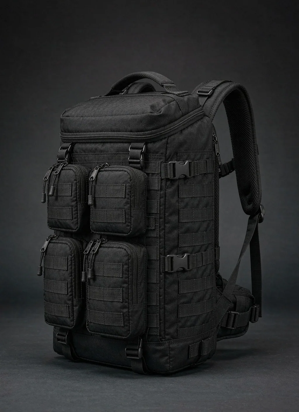
A modular backpack, including the best modular backpack configurations, pairs a stable carrier body with a controlled family of exchangeable modules. The useful definition is not simply a pack with loops: the carrier, interface geometry, load path, access logic, and module envelope must work as one documented platform. Buyers should therefore specify what remains fixed, what may be exchanged, how each attachment is verified, and which user task each configuration serves. A serious brief connects interface drawings to material callouts, pull and drop validation, packing method, and inspection criteria. Commercial planning also needs a realistic MOQ 500, sampling 6–10 working days, and mass production 35–50 days rather than a vague launch promise. This guide turns those requirements into an engineering and range-planning method. It covers platform levels, mounting technologies, third-party fit, module inventories, force paths, textiles, hardware, compliance evidence, SKU architecture, development gates, and recurring failure modes so that a purchasing team can compare systems on documented behavior instead of appearance or accessory count.
What a Modular Backpack Is—and What the Best Modular Backpack Platform Is Not
A useful modular architecture starts with a simple proposition: one carrier body supports a set of replaceable modules, and both sides of that relationship are deliberately designed. The carrier is not an empty canvas. It establishes the shoulder interface, back-panel behavior, primary volume, opening geometry, structural seams, and safe zones for attachment. The module is not merely a small container. It has an intended task, a controlled attachment footprint, an expected packed mass, an access direction, and a removal sequence. Between them sits the interface specification. That specification defines pitch, webbing width, field dimensions, mating materials, buckle families, allowable orientations, stitch placement, clearance, and test acceptance. When any part is undocumented, interchangeability becomes guesswork. A pouch may appear to fit while loaded forces peel the field, obstruct the main zipper, collapse the back panel, or move the center of gravity too far from the wearer. The core design question is therefore not whether something can be clipped on. It is whether the carrier and module continue to meet access, retention, comfort, and durability requirements in the intended configuration.
A modular platform is the enduring technical foundation. It includes the carrier pattern, graded material zones, structural reinforcement map, mounting-face geometry, interface control drawing, and validation envelope. A platform can survive a range refresh because new modules use the same controlled connection and stay within the same load assumptions. Color, module purpose, internal organization, and merchandising may change without disturbing the carrier tooling. Platform governance matters as much as the physical parts: drawings need datums, tolerances, approved hardware references, stitch definitions, and change control. If a buckle is replaced, a loop field changes pile density, or webbing drifts from the specified width, the platform may no longer be the same even when the marketing name remains. The platform level is where long-term compatibility is protected, where structural claims are bounded, and where a product team decides which interface features are open to outside modules and which remain controlled for safety or user experience.
A modular system is a market-facing selection built on that platform. It combines the carrier with a defined module family, packing rules, use cases, and configuration guidance. The same platform might support an administrative setup with a document panel and cable organizer, a field setup with exterior utility pockets and a hydration sleeve, or a travel setup with removable packing cells. A system should explain which modules can coexist, what access conflict each combination creates, where dense items belong, and which connection is secondary retention rather than primary support. System design also covers names, bill-of-materials options, inventory logic, replacement policy, and packaging. The word system is earned through coordinated behavior. A random assortment of accessories that share a clip does not provide the same assurance because no one has checked combination-level balance, zipper clearance, snag exposure, or cumulative load on the mounting face.
An add-on pouch is the lowest level. It may add useful storage to a compatible loop, rail, webbing row, or field, but the pouch alone does not turn an ordinary pack into a platform. An add-on often relies on a generic attachment claim and leaves the buyer to resolve pitch, retention, packed thickness, and release ergonomics. It may be appropriate where loads are light, removal is infrequent, and failure carries little consequence. The distinction becomes critical in procurement. If the requirement is occasional organization, a well-made add-on can be enough. If the requirement is a range that accepts future modules, supports shared inventories, and keeps fit predictable across deployments, the brief must be written at platform level. The best modular backpack is consequently not the version with the greatest number of exterior pockets. It is the platform whose controlled carrier, interfaces, modules, and validation envelope match the real work while minimizing unsupported combinations and unnecessary attachment weight.
| Architecture layer | Controlled scope | Required documentation | Typical buying error | Appropriate decision use |
|---|---|---|---|---|
| Modular platform | Carrier pattern, structural zones, attachment geometry, approved mating parts, and validated load envelope | Interface control drawing, reinforcement map, material specification, change record, and verification plan | Treating visible loops as proof that future modules will remain compatible | Long-lived product families, shared module inventories, and planned range extensions |
| Modular system | Named carrier and module combinations with packing and access rules | Configuration matrix, coexistence limits, user sequence, packing guidance, and system-level test record | Testing every component alone while ignoring interference between assembled parts | Audience-specific bundles, issue kits, retail packages, and operational setups |
| Add-on pouch | Local storage attached through a stated connector | Pouch dimensions, mating method, retention check, and intended contents | Assuming a generic attachment gives platform-level structural assurance | Light-duty organization, replacement accessories, and low-consequence additions |
Modular Backpack Platform Anatomy: Carrier, Mounting Face, Interfaces, and Modules
The carrier body performs the work that should not migrate with each configuration. Its main compartment establishes gross capacity, load containment, and opening behavior. A clamshell opening favors laid-out access but needs zipper paths that remain clear when exterior modules are full. A top opening protects the structural side seams but can make lower contents harder to reach. A panel opening can balance both behaviors if the hinge, zipper ends, and compression straps are coordinated. Inside, a suspended sleeve can isolate a laptop, hydration reservoir, radio, or document wallet from the floor impact zone. Dividers should not steal the volume promised to removable organizers. The base, shoulder-root area, grab handle, compression anchors, and lower corners deserve distinct material and stitch treatment because they transmit force rather than merely enclose contents. A frame sheet or shaped stay can preserve the back contour, prevent dense modules from printing through, and move load into the hip or lumbar region when the carry concept includes that support. None of these elements is decorative; each defines where the modular layer can safely act.
The mounting face is the platform’s working surface. A loop field accepts hook-backed organizers and identity panels, distributes light loads over area, and enables fine positioning, but contamination and peel direction require attention. A MOLLE panel based on PALS geometry gives repeatable woven retention; the control drawing should call out 25 mm webbing, 38 mm vertical spacing, and 50 mm horizontal repeat rather than relying on the word MOLLE alone. A daisy chain provides discrete lashing points and low material mass, yet it is not automatically equivalent to a woven PALS field. Fidlock V-BUCKLE hardware can create an intuitive guided closure where its mating orientation, strap path, and backup retention suit the task. Quick-release webbing built around an approved ITW/Nexus, Duraflex, or Woojin family can support familiar squeeze or pull actions, provided both halves are controlled as a pair. Magnetic attachment can help locate a module before mechanical engagement, but the magnet should not quietly become the sole load-bearing element unless a validated assembly was explicitly designed for that role.
Third-party compatibility needs a rule set, not a broad promise. The first rule is geometric: compare pitch, webbing width, mating depth, buckle size family, gate clearance, field dimensions, and the module’s occupied rows or columns. The next rule is mechanical: identify the primary force direction, likely peel edge, packed mass category, motion environment, and need for secondary retention. The next rule is operational: verify that the attached item does not block the main opening, compression path, shoulder adjustment, ventilation channel, helmet clearance, seated posture, or adjacent module release. Material interaction also matters. Aggressive hook can abrade light lining; a stiff tab can cut a coated textile; mismatched buckle halves may appear to latch without full tooth engagement; and magnetic parts may influence compasses or magnetically sensitive contents. A platform can publish an open geometric zone while reserving high-consequence locations for approved modules. That approach allows useful interoperability without converting every outside accessory into an implied structural claim.
The module inventory should be developed from tasks and packing behavior. External families may include a shallow administrative panel, vertical utility pocket, expandable dump pocket, bottle cradle, helmet or jacket beavertail, cable roll, medical organizer, radio pocket, tool sleeve, document wallet, and compression panel. Internal families may include hook-backed mesh pockets, padded electronics cells, removable dividers, key and credential panels, packing cubes, a hydration sleeve, and a protective insert. Carry-conversion parts may include a waist strap, shoulder sling, chest harness interface, or hand-carry panel when the platform has suitable anchors. Every module record should state attachment footprint, allowed mounting zones, access direction, compatible neighbors, intended content type, packed thickness, retention method, cleaning constraints, and replacement part references. Modules that carry dense contents need special scrutiny because a compact object can create a more severe local moment than a larger soft pocket. A disciplined inventory also prevents duplicate parts: if multiple concepts solve the same task with slightly different footprints, the platform loses the stock and compatibility advantages that modularity was meant to create.
| Module family | User task | Preferred mounting zone | Interface behavior to control | Combination caution |
|---|---|---|---|---|
| Administrative panel | Separate documents, writing tools, credentials, and small electronics | Front face or internal loop field | Flat support, controlled peel edge, and unobstructed opening | Dense chargers should sit near the carrier rather than at the outer wall |
| Utility pocket | Hold frequently reached field items | Front or side structural field | Woven retention or buckle support aligned with the packed center | A tall pocket can bridge the main opening or compression line |
| Bottle cradle | Secure a cylindrical vessel while allowing removal | Lower side zone with upper stabilization | Base support plus anti-swing control | Paired side loads should be packed with balance in mind |
| Expandable carry panel | Capture a jacket, helmet, or irregular soft item | Front anchors tied into structural seams | Compression force directed into reinforced anchor paths | Overfilling can obstruct vision behind the wearer or stress zipper edges |
| Medical organizer | Present categorized contents through a deliberate opening sequence | High-visibility front field or removable interior panel | Positive retention, clear pull direction, and glove-compatible release | Emergency access must not depend on removing unrelated modules |
| Electronics cell | Protect power, cables, and devices from impact and abrasion | Internal field near the back structure | Area attachment with anti-sag support | Heat, connector strain, and dense mass require packing guidance |
| Hydration sleeve | Contain a reservoir and route a drinking tube | Inside against the back panel | Vertical suspension and isolated hose routing | Leak containment and frame-sheet interaction need review |
| Tool sleeve | Index elongated implements and protect adjacent contents | Internal reinforced wall or controlled side field | Puncture resistance, closed lower stop, and top stabilization | Hard edges must not bear directly on coated fabric |
Interface Standards for a Modular Backpack: A Procurement Comparison
An interface comparison is only useful when the team separates the connector’s name from the capacity of the complete assembly. The upper load limit belongs to a tested chain: module textile, mating hardware, webbing or field, stitch pattern, reinforcement layer, carrier panel, and the seams that return force to the body. A strong buckle sewn to a lightly stabilized pocket can fail by fabric tear before the buckle approaches its catalog rating. Likewise, a broad loop field may hold a flat organizer well in shear but release earlier when a protruding pouch is peeled from an exposed edge. Procurement documents should therefore identify the weakest credible path and define the packed configuration used for verification. Catalog data for a component can support selection, yet it cannot replace pull and use testing on the assembled pack.
MOLLE/PALS is valuable where repeatable woven engagement, broad ecosystem familiarity, and field reconfiguration matter. Its penalty is threading time, added webbing, and the possibility of poor weaving that skips rows or leaves slack. Hook-and-loop fields provide fast placement and almost continuous positioning for light or supported modules, but holding behavior changes with field area, pile construction, contamination, temperature, wear, and peel leverage. Fidlock V-BUCKLE hardware supports guided alignment and an intentional release gesture; it performs best as a defined closure within a designed strap path, not as an undefined claim that any magnetic buckle can carry any module. Daisy chains are efficient lashing structures for clips, cords, or straps, but loop size and stitching determine behavior, and concentrated loading can distort the chain or base textile. Each interface has a credible domain when its force direction and user sequence match the connection.
ITW/Nexus quick-release components, along with approved Duraflex or Woojin equivalents where the tech pack permits them, offer familiar tactile confirmation and replaceable strap-based connections. Compatibility must be confirmed by exact family and mating halves; similar silhouettes are not evidence of reliable engagement. Pure magnetic attachment offers excellent alignment and silent, simple placement, but it is sensitive to separation distance and peel geometry. It is often most defensible as a locating aid paired with a mechanical latch, strap, rail, or captured pocket. For single-hand operation, evaluate the entire sequence while the bag is worn, placed on a surface, or accessed with gloves as the use case requires. A release that is easy in a fixture may be difficult when the pack moves away from the user, when adjacent fabric covers the actuator, or when tension jams the mechanism.
Life assessment also belongs at assembly level. Webbing can polish, hook can lose effective engagement, pile can mat, buckle edges can abrade a strap, daisy-chain stitches can loosen, and magnets can collect ferrous debris. Cleaning and field contamination may change performance before obvious breakage appears. Cost should include sewing time, reinforcement, mating controls, inspection, replacement inventory, and user training rather than hardware price alone. An apparently inexpensive daisy chain can become costly if it needs dense reinforcement and manual alignment; an apparently premium guided buckle can reduce assembly and user errors when the location is well suited. The comparison below uses qualitative capacity because no honest universal load ceiling exists across different panel constructions. The acceptance value must come from the project’s packed condition, safety margin, failure consequence, and verified test method.
| Connection technology | Defensible load-ceiling statement | One-hand handling | Service-life factors | Cost drivers | Best-fit applications |
|---|---|---|---|---|---|
| MOLLE/PALS | Potentially high when fully woven through controlled geometry and tied into a reinforced carrier; assembly test defines the ceiling | Slow for installation, stable in use, and generally not intended for instant removal | Webbing abrasion, stitch fatigue, skipped weaving, and deformation under dense local loads | Webbing consumption, alignment fixtures, sewing operations, reinforcement, and inspection | Field utility modules, stable exterior pockets, and ecosystems needing repeatable placement |
| Hook-and-loop field | Moderate in broad shear for supported modules; lower where a loaded edge creates peel | Fast placement and removal, though precise alignment may need the other hand | Pile matting, hook wear, lint, sand, moisture, heat, and repeated peel cycles | Field area, material grade, edge finishing, backing support, and replaceability | Internal organizers, identity panels, flat administrative modules, and light removable cells |
| Fidlock V-BUCKLE | Defined by the selected buckle, strap path, anchor construction, orientation, and backup strategy | Strong guided engagement and deliberate release when actuator clearance is protected | Strap wear, housing damage, debris, misorientation, and repeated loaded release | Hardware, precise mating layout, strap preparation, reinforcement, and approved-part control | Flaps, removable panels, compression features, and frequently operated closures |
| Daisy chain | Variable because loop length, stitch construction, base reinforcement, and loaded clip geometry dominate | Easy for simple clips; strap threading and tensioning may require more handling | Localized stitch loading, loop distortion, clip abrasion, and snag exposure | Webbing, repeated stitch operations, backing tape, and careful position control | Light lash points, cord routing, external gear capture, and adaptable strap paths |
| ITW/Nexus quick-release | Controlled buckle family and complete anchored strap assembly determine the verified limit | Familiar squeeze or pull action, subject to glove clearance and load direction | Latch wear, impact damage, grit, ultraviolet exposure, strap slip, and mismatched halves | Approved hardware family, paired inventory, strap ends, adjustment parts, and replacement plan | Compression straps, removable harness parts, lids, and modules needing positive tactile closure |
| Magnetic attachment | Usually best treated as alignment or secondary retention unless a dedicated assembly is validated | Excellent guided placement and simple release when peel direction is intentionally managed | Impact separation, collected debris, coating damage, corrosion protection, and separation distance | Magnet grade, encapsulation, polarity control, locating fixtures, and mechanical backup | Locating flaps, light panels, staged engagement, and closures backed by a positive restraint |
Load Engineering for the Best Modular Backpack: Force Paths, Reinforcement, and Balance
Load engineering begins by drawing the force path from the contents to the wearer, not by choosing a heavier face fabric. In the main compartment, gravity acts through the floor and side panels into structural seams, shoulder roots, and any frame or belt interface. An exterior module adds another path: its contents push against the module base, attachment tabs, mating field, carrier panel, reinforcement, and nearby seams before the force reaches the suspension. Walking introduces repeated acceleration and reversal; setting the pack down adds base impact; catching a projecting pouch adds peel and torsion; lifting by a grab handle redirects the entire packed mass through a concentrated anchor. A useful load map marks force direction, likely lever arms, hard-content contact points, and transitions between flexible and stiff materials. It should also distinguish continuous support from intermittent restraint. A top strap may stop sway but should not be mistaken for the base support that actually carries the module.
Reinforcement must connect the interface to structure. A bar-tack can lock webbing or arrest load at a defined point, but dense stitching in an unsupported textile may perforate the panel and create a tear line. The bar-tack length, thread, stitch density, webbing overlap, backing layer, and distance from an edge belong together in the specification. Running webbing through to a structural seam can spread force beyond a local patch and prevent the attachment face from behaving like a loosely applied label. Where the architecture permits, continuous webbing can pass behind the face or terminate in reinforced side, base, or yoke seams. A frame sheet or support board can control bulging, keep hard modules from pressing into the wearer, and distribute load across the back plane. It does not automatically strengthen an attachment, however; the interface still needs a defined connection to the supported structure. Foam can improve feel but compresses under load, so it should not be the only element expected to preserve geometry.
Drop and pull-off testing should reproduce credible failure directions. A development sequence can start with static pull on the primary attachment axis, continue with peel from vulnerable edges, then add angled loading, repeated manipulation, packed movement, and drops in representative configurations. The fixture must avoid creating an unrealistically strong or weak result. Clamping only the face textile may ignore how the real carrier is supported; gripping a module by a rigid plate may bypass the flexible packed behavior seen in use. Record the exact module, contents or surrogate, mounting position, weaving or latch procedure, conditioning, carrier support, loading direction, endpoint, and observed damage. Pass criteria can include no release, no safety-critical seam propagation, no unacceptable deformation, maintained access, and continued function after the event. ASTM D5034 can inform textile tensile evidence, but an assembled attachment test needs its own project method because tensile strength alone does not describe stitch pull-out, peel, buckle release, or panel deformation. Test planning should also define conditioning before force is applied. A clean, dry development sample gives a useful baseline, yet an interface may behave differently after moisture exposure, dust, repeated opening, compression in transit, or storage with a module attached. Conditioning should reflect credible service rather than an arbitrary torture sequence. Hook-and-loop fields benefit from checks after repeated mating and contamination because loss of effective contact may start at the edges. Webbing systems should be inspected for polishing, yarn damage, stitch migration, and adjuster slip. Guided buckles need debris, partial-engagement, and off-axis reviews. Coated panels should be examined around needle holes and folds, where stiffness transitions can concentrate damage. The test record should distinguish preconditioning damage from damage created during the measured event so a team can trace the mechanism instead of debating a final photograph without context. Configuration selection matters just as much as conditioning. A broad, shallow organizer may create high total shear but limited peel, while a compact dense pocket can create a severe moment at its upper anchor. The verification matrix should include the module with the most demanding leverage, the location with the least structural support, the combination that crowds an opening, and the asymmetric setup most likely to disturb balance. Testing only the heaviest module can miss a lighter shape with a longer lever arm. Testing only the center of a mounting field can miss an edge position where the reinforcement terminates. When modules share a mounting method, engineering judgment can group equivalent constructions, but the rationale for that grouping should be recorded against geometry, packed behavior, materials, and force direction. A change in any of those factors can trigger focused revalidation even if the module name stays the same. Acceptance language needs observable boundaries. Terms such as durable, secure, or heavy duty are not test endpoints. A release document should state whether temporary deformation is acceptable, whether stitching may move without breaking, whether a module may shift while remaining captured, whether the carrier must remain fully usable, and which damage is considered cosmetic rather than structural. It should identify critical functions that must continue after the event, such as shoulder retention, content containment, zipper operation, and deliberate module removal. Failure should be classified by origin and consequence. A replaceable module tearing in a sacrificial way may have a different implication from a carrier panel splitting into the main compartment, but that behavior must be intentional and supported by the use case. Where a safe failure mode is desired, the sacrificial part should release predictably without creating sharp hardware, loose dense contents, or progressive damage to the carrier. Test execution should preserve traceability. Record the sample revision, material lots where available, component references, sewing construction, operator mounting sequence, conditioning, fixture contact, loading direction, and result. Photographs should show the complete setup as well as the failure origin; close views alone can hide an unrealistic clamp or unsupported carrier. Instruments and fixtures should be suitable for the method, and any deviation should be documented before results are used for release. Retained references help compare later production and investigate field reports. If a failure leads to reinforcement, changing only the sample is not enough: the tech pack, bill of materials, operation description, inspection point, and approved reference need the same revision. Retesting should then target both the original mechanism and any new stiffness transition created by the correction. This discipline turns a pull result into design evidence and keeps an isolated development success from becoming an uncontrolled production assumption.
Center of gravity changes every time a module moves mass away from the back, upward, downward, or to one side. A shallow dense module placed close to the back plane generally creates less rearward moment than the same contents in a deep front pouch. High mounting may keep an item accessible but can amplify sway; low mounting can interfere with lumbar movement or strike surfaces; side mounting can produce persistent asymmetry. Packing guidance should reserve back-adjacent zones for dense contents, use front positions for lighter and compressible items, and encourage balanced side loads. Compression should draw the complete load toward the carrier rather than merely flattening an empty outer pocket. The team should evaluate balance with each proposed module combination, with expected clothing and posture, and during turns, steps, bending, and seated use. The best modular backpack is not balanced in only its base configuration. It remains manageable across the approved system matrix, or it clearly excludes combinations that move mass outside the validated envelope.
| Validation activity | Engineering question | Representative setup | Evidence to capture | Release criterion concept |
|---|---|---|---|---|
| Force-path review | Does every loaded interface return force to a structural seam, panel, or support? | Marked sample with carrier, reinforcement, module, and suspension layers visible | Annotated path, material transitions, stitch callouts, and unsupported spans | No critical attachment depends on decorative skin or compressible foam alone |
| Primary-axis pull | Can the complete attachment resist loading in its intended support direction? | Production-representative carrier and packed module mounted exactly as instructed | Load-displacement behavior, seam movement, webbing slip, and failure origin | Project acceptance reached without release or unacceptable damage |
| Edge-peel challenge | Will an exposed corner initiate progressive detachment? | Vulnerable module edge loaded away from the carrier under realistic support | Peel start, field distortion, local stitch response, and remaining retention | No uncontrolled propagation within the approved use envelope |
| Angled snag simulation | How does the assembly react when a projecting module catches an obstacle? | Loaded pocket acted on from likely travel and handling directions | Rotation, anchor stress, fabric tearing, hardware damage, and carrier access | Failure behavior is contained and does not compromise essential carry structure |
| Packed drop assessment | Do impact and inertia expose weak anchors or hard-content contact points? | Complete approved configuration packed according to the test record | Impact orientation, module release, floor damage, zipper function, and frame condition | Required retention, containment, and access remain functional after evaluation |
| Movement and balance trial | Does the configuration remain stable and wearable through intended motion? | Approved packed setups evaluated through walking, turning, bending, and seated posture | Sway, pressure, strap migration, access conflict, and user compensation | No unacceptable imbalance, pressure concentration, or interference is observed |
Materials and Hardware for a Modular Backpack: Evidence Before Labels
Material selection should follow zone function. 500D Cordura can provide a practical balance of abrasion performance, hand, sewing behavior, and mass for many carrier shells and module faces. 1000D Cordura may suit severe contact zones or applications where abrasion and rough handling outweigh the penalty in stiffness, bulk, and sewing effort. Using the heavier option everywhere can make a platform harder to fold, less comfortable at seam stacks, and needlessly expensive without solving attachment-path weakness. A 210D–420D lining range can support internal organization, contrasting visibility, and lower bulk, but lining grade should be matched to pocket contents, seam type, coating, and cleaning exposure. Hard tools, battery corners, hook surfaces, or removable dividers can abrade a light liner even when the outer shell remains intact. Reinforcement textiles, binding, spacer mesh, foam, board, and nonwoven backing should be specified as functional layers rather than hidden substitutions left to sample interpretation.
Coatings and DWR have different jobs. A back coating can contribute resistance to water passage, fray control, dimensional behavior, and coating adhesion characteristics, while DWR helps water bead and delays surface wetting. Neither term alone justifies a finished-product claim. Seams, needle holes, zipper paths, openings, interface stitches, and coating damage govern real exposure. AATCC 127 provides a recognized hydrostatic-pressure method for textile evidence; ASTM D751 addresses tests relevant to coated fabrics; ASTM D5034 supports grab tensile measurement; and ISO 6330 provides domestic washing and drying procedures useful when care validation calls for laundering. The project should record the exact substrate, color, finish, conditioning, and lot associated with reports. A result for a nominally similar textile is not automatically transferable when denier, weave, coating chemistry, color treatment, or finishing route changes. DWR expectations should also consider target-market chemical restrictions and the intended maintenance message.
Zipper sizing must reflect path shape, packed pressure, access frequency, slider handling, and repair consequences. YKK #5 can be appropriate for organizer openings and lighter internal access where flexibility and reduced bulk matter. YKK #8 offers a more substantial path for many main compartments or loaded pockets. YKK #10 can suit demanding main openings or areas with higher separation forces, provided the surrounding tape, seam, corners, and garage are engineered accordingly. A larger chain does not correct a sharp zipper turn, poor seam allowance, excessive overpack, or a slider trapped by an exterior module. Specify chain type, gauge, slider arrangement, puller, tape color, end treatment, and any water-resistant construction without reducing the callout to a brand name. Test access when neighboring modules are packed, compression is engaged, and the carrier is on-body or supported as users will handle it.
Buckles and adjusters from Duraflex, Woojin, ITW/Nexus, or another approved component family need exact references and paired-part control. Brand mixing or silhouette matching can produce incomplete engagement, unexpected release force, strap slip, or replacement confusion. For 25 mm webbing, specify fiber, weave, thickness, hand, finish, color tolerance, and compatibility with each adjuster. A slick strap may creep through a ladder lock; a thick strap may resist adjustment or prevent full buckle closure. Webbing ends, folds, bar-tacks, box patterns, and anchor overlap should be visible in the tech pack. Hardware should be reviewed for impact, temperature, chemical exposure, edge sharpness, and contact with coated textiles. Material approval works best as a traceable set: approved swatches, component boards, test reports, color standards, construction samples, and an exception process. That package allows the production team to preserve function when a component needs review instead of making an undocumented substitution based on appearance.
| Specified element | Design rationale | Relevant evidence route | Construction dependency | Approval note |
|---|---|---|---|---|
| 500D Cordura shell zone | Balanced abrasion response, manageable seam stacks, and practical carrier hand | Identity, shade, finish, ASTM D5034 tensile evidence, and project abrasion review | Seam type, backing, coating, binding, and interface reinforcement | Approve actual color and finish rather than a generic fabric description |
| 1000D Cordura contact zone | Added robustness where surfaces receive concentrated abrasion or rough placement | Material identity, tensile evidence, coating record, and handling assessment | Needle selection, fold thickness, edge treatment, and transition to lighter panels | Use selectively where the zone analysis justifies stiffness and mass |
| 210D–420D lining | Internal visibility, containment, organization, and reduced bulk | Tear and seam review, colorfastness route, coating check, and ISO 6330 care validation where applicable | Pocket contents, hook shielding, seam allowance, binding, and hard-edge isolation | Approve by intended pocket duty rather than denier alone |
| Coating and DWR | Manage wetting, water passage, fray, and textile behavior | AATCC 127, ASTM D751, chemistry declaration, and finish-lot traceability | Needle holes, seam design, zipper construction, and abrasion during assembly | State a bounded performance description supported by the finished construction |
| YKK #5/#8/#10 zipper system | Match opening duty, curvature, packed force, and handling needs | Approved chain and slider references plus operated packed-sample review | Tape seam, corner radius, end stops, garage, compression, and neighboring modules | Control the complete zipper assembly rather than chain gauge alone |
| Duraflex, Woojin, or ITW/Nexus hardware | Provide controlled release, adjustment, and positive mating behavior | Exact component reference, mating check, impact review, and assembly pull test | Webbing thickness, strap path, anchor reinforcement, and actuator clearance | Paired halves and replacements remain within the approved family |
| 25 mm webbing | Carry interface loads, form PALS geometry, or support closures and adjustment | Fiber and weave identity, width check, tensile route, and adjuster slip assessment | Bar-tack, overlap, backing layer, edge distance, and continuous force path | Control hand and thickness because nominal width does not ensure hardware fit |
Product-Line Architecture: Turning One Modular Backpack Platform into 6–12 SKUs
A platform creates commercial leverage when variation moves into controlled modules rather than new carrier patterns. The shared carrier should hold the expensive and fit-sensitive decisions: back geometry, shoulder pattern, main opening, structural seams, base, reinforcement map, mounting fields, and core material zones. Audience differentiation can then come from module selection, internal organization, color direction, packing guide, and merchandising. This approach avoids reopening pattern development every time a channel requests a different use case. It also concentrates validation on the common structural base while making configuration-specific checks manageable. The principle is not that every conceivable audience receives the same object. It is that approved variation stays inside an architectural boundary. If a requested setup needs a different torso fit, suspension class, main volume, or structural load path, it may justify another platform rather than a forced module bundle.
Planning a range of 6–12 SKUs starts with task clusters. Identify what every target user carries, what must remain immediately accessible, what is dense or fragile, what can be removed at destination, and what should never share a compartment. Translate those findings into a small module grammar: flat organization, protected electronics, expandable soft carry, side retention, tool isolation, and rapid-access utility. A SKU is then a controlled configuration of the carrier plus selected grammar elements, not a new sewing pattern disguised by a new name. The bill of materials can separate common carrier content from configuration kits so purchasing, assembly, and replacement inventory remain visible. Marketing names may differ, but internal configuration codes should map directly to module lists and approved mounting positions. This prevents a late packaging decision from changing structural behavior without review.
Price bands should be built from module complexity and included value rather than weakening the common carrier. An entry configuration can offer the same structural body with minimal removable organization. A core band can add task-specific modules that improve access and separation. A premium band can combine protected cells, guided hardware, or more elaborate presentation where the audience values those features. The carrier’s safety-critical materials, shoulder attachment, interface geometry, and verification should not quietly decline at the lower band, because that would fragment the platform and complicate claims. Any quoted pricing is indicative only, FOB Xiamen, 500-unit MOQ. Cost reviews should expose hardware, sewing operations, reinforcement, packaging, inspection, and module assembly so the team can remove low-value complexity without damaging the force path or interchangeability.
Range governance prevents SKU drift. Maintain a configuration matrix showing allowed module locations, incompatible pairs, packing assumptions, color and trim options, compliance variants, and packaging contents. New proposals should pass an architecture review before artwork or sales commitment. The review asks whether the idea uses an existing module, needs a new module within the established interface, or exceeds the platform envelope. A new module should reuse approved materials and hardware where practical, but reuse must not override function. Version control is essential when a field dimension, buckle, hook grade, or reinforcement changes because old and new modules may look interchangeable while behaving differently. A clear compatibility mark, revision record, and replacement policy protect the installed base. With that discipline, the platform can support coherent audience stories without multiplying hidden constructions and test obligations.
| Range configuration | Common carrier basis | Included module combination | Primary audience | Positioning band | Configuration rationale |
|---|---|---|---|---|---|
| Essential platform | Shared carrier shell and mounting map | Flat internal organizer and basic compression set | General program buyer needing a neutral starting point | Entry | Preserves the validated body while minimizing task-specific inventory |
| Administrative setup | Shared carrier shell and mounting map | Document panel, cable roll, and credential organizer | Mobile office and service coordination teams | Core | Moves small-item order into removable components without changing the main opening |
| Technical service setup | Shared carrier shell and mounting map | Tool sleeve, parts cells, and protected electronics module | Inspection, maintenance, and field support crews | Premium | Isolates hard tools and dense equipment near reinforced carrier zones |
| Travel organization setup | Shared carrier shell and mounting map | Removable packing cells, document wallet, and cable organizer | Frequent travel and deployment teams | Core | Supports destination removal while keeping the carrier architecture unchanged |
| Outdoor utility setup | Shared carrier shell and mounting map | Bottle cradle, expandable carry panel, and internal hydration sleeve | Outdoor programs and mobile crews | Core | Controls soft exterior carry and keeps water close to the back plane |
| Rapid-access setup | Shared carrier shell and mounting map | Front utility pocket, high-visibility organizer, and guided closure panel | Users prioritizing deliberate access under movement | Premium | Coordinates opening sequence instead of adding unrelated exterior pockets |
| Electronics protection setup | Shared carrier shell and mounting map | Suspended device cell, power organizer, and cable routing panel | Technical, media, and equipment-management teams | Premium | Places dense protected contents close to the structural back and separates connectors |
| Light utility setup | Shared carrier shell and mounting map | Shallow exterior pouch and removable mesh cells | Programs needing simple issue and easy visual inventory | Entry | Adds visible organization with limited depth and a restrained module count |
Commercial Development of a Custom Modular Backpack and Compliance Control
A custom modular backpack program should begin with a bounded brief rather than a collage of features. The brief identifies target market, user tasks, carrier volume logic, approved module count, interface choice, packed-content categories, target cost position, expected order profile, packaging route, and compliance destination. It should separate mandatory behavior from preferences so engineering trade-offs remain visible. Commercial baselines are MOQ 500, sampling 6–10 working days, with complex sampling 12–15 working days, and mass production 35–50 days after approvals and required inputs are complete. Payment terms are T/T 30/70, and the commercial basis is FOB Xiamen. Those numbers need to stay attached to assumptions about materials, hardware availability, artwork, testing, and approval response; changing the interface family or adding modules after sample review can reopen development work and the critical path.
The development flow is brief → tech pack → prototype → small-batch validation → mass production. During the brief stage, the team resolves audience, configuration, interface, load cases, and evidence needs. The tech pack converts intent into measurable control: patterns, dimensions, tolerances, materials, hardware references, stitch construction, reinforcement, logo treatment, module map, labels, packaging, and test plan. The prototype stage is for learning rather than cosmetic approval alone. Review fit, access, packing, weave or latch sequence, center of gravity, seam behavior, and module combinations. Small-batch validation checks whether the documented construction can be repeated, inspected, packed, and used without relying on sample-room judgment. Only then should the approved sample, signed records, bill of materials, and inspection criteria become the mass-production reference.
Quality planning should define incoming checks, in-process controls, final inspection, and test records around platform risks. AQL 2.5 provides the stated final inspection level, with sampling grounded in ISO 2859-1, whose historical predecessor is MIL-STD-105. The defect library should distinguish critical retention or safety issues from major function defects and minor appearance variation. Examples include incomplete buckle engagement, skipped PALS weaving, missing reinforcement, zipper obstruction, webbing misalignment, module interference, uncontrolled shade differences, and incorrect kit contents. Final inspection cannot replace process control because hidden backing, webbing overlap, and stitch paths may no longer be visible. The production team should use approved component boards, first-piece checks, seam and attachment verification, configuration audits, and packaging reconciliation to keep the system aligned with the signed tech pack.
Compliance is a documented market-access process, not a logo collection. REACH (EC 1907/2006) supports chemical-substance control for relevant European market obligations. California Prop 65 requires exposure-based review and appropriate decisions for products entering California. CPSIA becomes relevant when the product scope and intended user bring it within applicable consumer-product requirements, especially where children’s product rules may apply. OEKO-TEX Standard 100 can provide useful textile and component substance evidence within its certified scope. ISO 9001 describes a quality-management-system framework, while BSCI addresses a social-compliance monitoring framework; neither proves the performance of a particular backpack. ISTA 3A can inform packaged-product distribution testing for applicable parcel conditions. Evidence should map to actual materials, trims, colors, print systems, production route, and destination. The compliance file needs declarations, reports, certificates with scope and validity, risk assessment, bill-of-material links, packaging evidence, and a change-control trigger when anything relevant is substituted.
| Program phase | Decision objective | Core deliverables | Exit evidence | Common hold point |
|---|---|---|---|---|
| Brief | Define the use case and platform boundary before detail work begins | User tasks, content categories, interface direction, module plan, market, and commercial assumptions | Agreed priorities, exclusions, evaluation conditions, and review owners | Conflicting audience needs or an undefined packed-load assumption |
| Tech pack | Translate approved intent into measurable construction controls | Drawings, dimensions, tolerances, materials, hardware, seams, reinforcement, labels, and test plan | Controlled revision ready for prototype execution and component approval | Generic hardware names, missing mating references, or no interface datum |
| Prototype | Discover fit, access, balance, attachment, and assembly problems | Representative carrier, modules, review checklist, packed trial, and issue log | Closed or assigned findings with updated specifications and accepted direction | Cosmetic sign-off attempted before structural and configuration review |
| Small-batch validation | Verify repeatability, inspection visibility, kitting, and packaging | Controlled run, in-process records, configuration audit, and distribution pack | Stable construction, resolved defects, approved inspection criteria, and retained references | Hidden operations depend on individual judgment rather than defined controls |
| Mass production | Execute the approved configuration under controlled changes | Approved bill of materials, reference sample, production checks, AQL 2.5 inspection, and shipment file | Conforming inspection result, correct kits, traceable evidence, and release authorization | Unapproved material, hardware, artwork, or module substitution |
| Review framework | Primary control question | Useful file evidence | What it does not establish | Change trigger |
|---|---|---|---|---|
| REACH (EC 1907/2006) | Are relevant substances controlled for the materials and destination obligations? | Material declarations, scoped reports, bill-of-material mapping, and risk review | Mechanical durability or universal approval for every market | Textile, coating, print, adhesive, plating, or trim change |
| California Prop 65 | Has exposure risk for California distribution been assessed and addressed? | Substance information, exposure review, material traceability, and decision record | A blanket statement that no warning analysis is ever needed | Chemistry, use pattern, contact profile, or destination change |
| CPSIA | Does intended use create applicable consumer-product obligations? | Product classification, component evidence, test records where applicable, and tracking information | Automatic coverage for products outside the relevant scope | User-age positioning, component, coating, or labeling change |
| OEKO-TEX Standard 100 | Are certified materials and components used within the certificate scope? | Valid certificate, scope details, article references, color coverage, and purchase traceability | Finished-pack structural performance or coverage beyond listed articles | Material source, finish, color, print, or certificate-status change |
| ISO 9001 | Does the audited quality system cover relevant processes and current scope? | Certificate, scope, validity, audit status, and process records | Conformance of an individual shipment without product inspection | Scope, site, process ownership, or certificate-status change |
| BSCI | Is current social-compliance evidence available for the relevant production route? | Audit record, scope, status, corrective-action follow-up, and facility mapping | Product chemistry, load capacity, or shipment quality | Production-route or audit-status change |
| ISTA 3A | Can the packed configuration tolerate the defined parcel-distribution sequence? | Test plan, package specification, packed sample record, results, and damage review | Performance under every freight mode or a different package configuration | Carton, protective material, kit mass distribution, or pack-out change |
Failure Modes, Validation Gates, and How to Select the Best Modular Backpack
Recurring failures usually reveal an architecture gap rather than a single bad component. A pouch that tears away may point to an interrupted force path, not weak face fabric. A buckle that opens under movement may be correctly molded but poorly oriented, incompletely engaged, exposed to accidental actuation, or paired with the wrong half. A loop field that performs well in a flat pull may fail when a thick module creates peel. A carrier that feels comfortable when empty may rotate backward after an exterior configuration moves dense contents away from the back. The corrective method is to identify the physical mechanism, locate it in the approved use sequence, and change the design or configuration boundary that allowed it. Simply specifying heavier materials can move the failure into a seam, add weight, and leave the underlying leverage untouched.
Validation gates should mirror the order in which uncertainty is reduced. Architecture review confirms that the carrier, interface, and module family have coherent roles. Component review confirms exact textiles, webbing, zippers, buckles, hook and loop, magnets, boards, foams, and threads. Construction review verifies reinforcement paths, stitch placement, seam allowances, and access clearances. Configuration review checks all approved module combinations, not just the most photogenic setup. Packed verification then evaluates pull, peel, movement, drops, zipper operation, compression, and balance. Care and contamination review examines how dirt, moisture, cleaning, and repeated attachment affect behavior. Packaging review confirms that modules arrive undamaged, correctly paired, and clearly identified. Production release occurs only when drawings, samples, evidence, inspection criteria, and open issues agree.
Selecting the best modular backpack requires a weighted decision based on program needs. Begin with platform integrity: Does the carrier remain useful without unnecessary modules, and are loaded interfaces tied into structure? Examine compatibility discipline: Are geometry, mating references, mounting zones, and revisions documented? Review user operation: Can intended users find, release, replace, and secure modules under realistic posture, clothing, and visibility? Check range logic: Do configurations solve distinct tasks while sharing a genuine carrier base, or do they create inventory noise? Examine evidence: Are material reports, assembly tests, compliance records, inspection plans, and packaging validation tied to the actual bill of materials? Finally, look at lifecycle behavior: Can damaged modules be replaced without discarding the carrier, can old and new revisions be identified, and can the approved system absorb a future module without reopening its foundations?
A procurement scorecard should avoid false precision. Rate evidence quality, not merely the presence of a feature. A documented PALS drawing is stronger than a generic MOLLE claim. A tested loaded assembly is stronger than a buckle data sheet. A configuration map is stronger than a photograph showing many accessories. A scoped certificate is stronger than an unsupported compliance logo. Record exclusions and assumptions next to every score so the result survives team changes. The right outcome may be a restrained platform with fewer approved modules, because controlled interoperability is more valuable than unlimited theoretical attachment. The aim is a carrier that protects its structural and ergonomic functions while allowing useful, replaceable task layers. When interface control, load engineering, materials, evidence, range governance, and production discipline align, modularity reduces redevelopment and inventory complexity instead of adding failure points.
| Observed failure mode | Likely mechanism | Early diagnostic sign | Preventive action | Verification focus |
|---|---|---|---|---|
| Mounting field tears from the carrier | Attachment force stops in the face panel rather than continuing into structure | Panel puckering, stitch-line whitening, or localized distortion during packed handling | Connect reinforcement or continuous webbing to structural seams and review edge distance | Primary-axis pull, angled loading, and post-test seam inspection |
| Hook-backed module peels unexpectedly | Thick load creates leverage at an exposed field edge or contamination reduces engagement | Corner lift, audible progressive release, or reduced field contact after packing | Increase supported area, shield the peel edge, reduce depth, or add positive secondary retention | Edge-peel challenge after conditioning and repeated use |
| PALS module sags or bounces | Webbing is skipped, pitch drifts, or the module lacks lower stabilization | Visible gap between pouch and carrier or movement during walking | Control 25 mm webbing, 38 mm vertical spacing, 50 mm horizontal repeat, and weaving instructions | Geometry audit plus packed movement assessment |
| Quick-release opens in motion | Actuator is exposed, buckle halves mismatch, or load direction promotes release | Partial latch, inconsistent tactile confirmation, or contact with adjacent equipment | Use controlled mating parts, protect the actuator, and orient the buckle to the force path | Engagement check, angled pull, impact review, and gloved operation |
| Main zipper becomes inaccessible | Module footprint crosses the opening path or packed thickness covers the slider | Slider collision, forced zipper angle, or need to remove a module for routine access | Define keep-clear zones and verify neighboring modules at representative fill | Repeated opening with approved packed configurations and compression engaged |
| Carrier pulls backward from the wearer | Dense contents sit in deep exterior modules far from the back plane | Shoulder pressure, forward posture compensation, or lower-pack bounce | Reserve outer zones for lighter contents and place dense modules close to structural support | Center-of-gravity review and movement trial across configuration matrix |
| Side loading creates persistent imbalance | Single dense side module is not counterbalanced or stabilized | One shoulder strap tightens more, carrier rotates, or contents swing during turns | Pair side loads, relocate dense contents, or restrict the mounting zone | Asymmetric packed-use assessment in intended posture |
| Webbing creeps through an adjuster | Webbing hand, thickness, finish, and hardware geometry are incompatible | Strap length changes under cycling or needs repeated readjustment | Approve webbing and adjuster as an assembly and control finish and routing | Loaded slip assessment before and after conditioning |
| Coating cracks near attachment stitches | Stiff coating, dense perforation, fold stress, or abrasion concentrates at the seam | Surface whitening, flaking, pinholes, or delamination around the stitch line | Adjust material, needle, stitch pattern, backing, and fold geometry as a set | Flexing, visual inspection, and relevant ASTM D751 evidence |
| Old and new modules no longer mate reliably | Undocumented interface revision or component substitution changes geometry | Inconsistent engagement, field complaints limited to mixed production dates, or forced assembly | Apply revision control, compatibility marking, paired-part governance, and retained references | Cross-revision fit matrix and replacement-part audit |
Frequently asked questions
What is a modular backpack?
A modular backpack is a controlled carrier body paired with exchangeable modules through documented interfaces. The carrier preserves suspension, main capacity, structural seams, and safe attachment zones. Modules add task-specific organization or carry functions. A true platform defines geometry, materials, mating parts, allowed positions, and validation conditions, so an attached pouch alone does not establish modular architecture.
How is a modular platform different from a modular system?
The platform is the technical foundation: carrier pattern, reinforcement map, mounting geometry, approved interfaces, and change control. The system is an approved market or user configuration built on that foundation, including selected modules, packing rules, compatibility limits, and access sequence. Multiple systems can share one platform when they remain inside its validated boundaries.
Does adding a MOLLE pouch make any backpack modular?
No. A pouch may add useful storage, but platform status requires controlled PALS geometry, a load path into reinforced structure, compatibility rules, and assembled validation. If webbing is decorative, poorly spaced, or sewn only to a light face panel, the connection may not support the packed module even when it looks compatible.
What PALS dimensions should a technical brief control?
The brief should control 25 mm webbing, 38 mm vertical spacing, and 50 mm horizontal repeat, together with row alignment, stitch placement, backing construction, and usable clearance. The dimensions help establish geometric fit, but verified capacity still depends on the complete carrier, module, weaving method, reinforcement, seams, and packed condition.
Is hook-and-loop suitable for load-bearing modules?
It can support suitable modules when field area, shear direction, peel exposure, backing, contamination, and packed leverage are controlled. It is particularly useful for flat internal organization. Thick or dense exterior modules can create peel at an edge, so they may need another support method or positive secondary retention validated with the actual assembly.
Can magnetic attachment serve as the only retention method?
Only when the specific assembly has been designed and validated for its load directions and consequences. Magnetic force changes with separation and peel geometry, while impacts or debris can alter behavior. In many backpack applications, magnets are better used for alignment or guided closure alongside a mechanical latch, strap, captured edge, or other positive restraint.
How should third-party module compatibility be assessed?
Compare interface pitch, webbing width, buckle family, mating depth, field size, occupied footprint, clearance, and orientation. Then evaluate packed mass, peel risk, access interference, snag exposure, center-of-gravity change, and material interaction. Compatibility should be stated for defined zones and conditions rather than as an unlimited promise based on appearance.
Why does center of gravity matter after modules are attached?
External modules move mass away from the back or toward one side, increasing leverage, sway, and pressure even when total contents do not change. Dense items belong close to the structural back plane, while outer zones are better for lighter, compressible contents. Every approved configuration should be assessed in motion and realistic posture.
What is the role of bar-tack reinforcement?
A bar-tack can secure webbing and concentrate stitches where a defined load enters an anchor. It is effective only when thread, density, overlap, backing, textile strength, and edge distance work together. Dense stitching in an unsupported panel can create perforation and tearing, so the complete force path matters more than the stitch name.
Which zipper gauges are commonly specified for platform development?
YKK #5/#8/#10 are the controlled gauge references in this program framework. Selection depends on opening duty, curvature, packed pressure, handling, and repair consequence. The chain must be reviewed with slider, tape seam, end treatment, corner geometry, compression, and neighboring modules because a larger gauge cannot correct a poor zipper path.
How should 500D and 1000D Cordura be allocated?
500D Cordura can balance abrasion response, hand, mass, and sewing behavior across many shell areas. 1000D Cordura can be reserved for demanding contact zones where its added stiffness and bulk are justified. Zone-based allocation is preferable to using the heavier textile everywhere, and neither choice replaces structural reinforcement at loaded interfaces.
What do AATCC 127 and ASTM D751 show?
AATCC 127 provides a hydrostatic-pressure method for textile resistance to water passage. ASTM D751 covers test methods relevant to coated fabrics. Their reports can support material decisions when tied to the actual substrate, coating, color, finish, and lot, but they do not by themselves establish finished-pack behavior across seams, zippers, and attachment needle holes.
What does ASTM D5034 contribute to a modular pack program?
ASTM D5034 supplies grab tensile evidence for textiles. It helps compare or qualify material behavior, but it does not replace an assembly pull test. Module retention also depends on stitching, webbing overlap, backing, buckle orientation, panel support, peel direction, and structural seams, which require project-specific verification on a representative pack.
How can one carrier platform support 6–12 SKUs?
Keep suspension, carrier pattern, structural seams, opening, reinforcement map, and mounting fields common. Create audience differentiation through approved module combinations, internal organizers, color choices, packing guidance, and presentation. Each SKU then maps to a controlled configuration rather than a new carrier pattern, while exceptions that alter fit or load path trigger a platform review.
What commercial terms apply to a custom modular backpack program?
The stated framework is MOQ 500, sampling 6–10 working days, complex sampling 12–15 working days, mass production 35–50 days, AQL 2.5, T/T 30/70, and FOB Xiamen. Timing assumes that the brief, tech pack, materials, artwork, tests, and approvals proceed without a change that reopens interface or construction development.
Which compliance records should a procurement file contain?
The file should map relevant REACH (EC 1907/2006), California Prop 65, CPSIA, and OEKO-TEX Standard 100 evidence to actual materials and destination scope. It should also retain applicable ISO 9001 and BSCI scope records plus ISTA 3A packaging evidence where used. Certificates need validity, scope, traceability, and change-control review.