Home › MOLLE System
Field-tested modular load carriage
MOLLE System Engineering for MOLLE Backpacks, Pouches and Attachments
A MOLLE backpack earns the name only when the attachment face is built to controlled PALS geometry: 25 mm webbing, 38 mm row pitch, 50 mm column repeat, a defined backing stack, and stitch anchoring that returns pouch load into structural seams. That set of callouts is what lets MOLLE pouches and MOLLE attachments from separate production lots weave tight and stay tight; the word MOLLE printed on a hangtag proves nothing about pitch, backing or anchoring. This page addresses civilian load carriage only, covering outdoor programmes, worksite kits, response and first-aid modules, field electronics handled by licensed operators, and organised daily carry. Not covered here: weapon carriage, ammunition storage, ballistic protection or controlled capability of any kind; nothing below is presented as defence-approved product. The sections below move from grid geometry through face construction, force direction, usable area, stitch control, outside-part acceptance, failure diagnosis, rival attachment technologies, laboratory routes and commercial terms built on MOQ 500, sampling 6–10 working days and mass production 35–50 days.
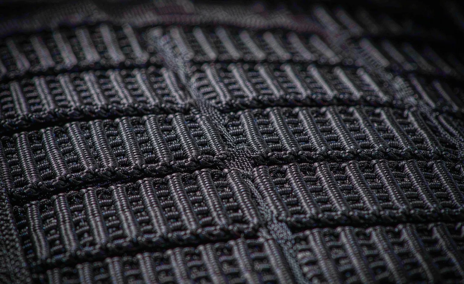
PALS Geometry: Why Printing the Word MOLLE Is Not a Specification
The term MOLLE began as a programme name for a family of load-carriage equipment. The grid that actually receives a pouch is the PALS array, and it is the array a buyer has to specify. Writing the programme name into a tech pack without dimensions hands the sewing room a slogan instead of a drawing. What belongs on that drawing is webbing width, row pitch, column repeat, stitch island length, backing construction, end anchoring, edge distance, and the number of rows a mounted item is expected to engage. With those items controlled, two pouches made a year apart in separate lots weave and sit in the same way. Without them, a panel can photograph perfectly and still refuse a strap, or accept the strap and then drop the pouch under load.
Three dimensions carry most of the fit behaviour. 25 mm webbing sets the channel a pouch strap must pass through; a strap cut for that width will not thread a narrower row, while an oversized row wastes face area and permits twist. 38 mm vertical spacing sets the weave step, meaning the distance a strap travels between one passage and the next, which decides how many rows a given pouch height can engage and how much bearing area the weave develops. 50 mm horizontal repeat sets the stitch islands, the sewn segments that interrupt each row and open the gaps a strap enters. Islands are structural rather than decorative, because every load a pouch applies reaches them before it reaches the panel behind.
Those three values describe geometry and nothing else. A buying document also needs the tolerance band, the nominal row count, the columns genuinely usable, island length and its end treatment, the backing stack behind the field, and the distance from the outermost row to the panel edge or adjacent seam. None of that can be read from a photograph. It is entirely possible to build rows at correct pitch on a face panel with no reinforcement behind them, in which case the field behaves like an applied label instead of a load path. It is equally possible to hit every dimension and still produce a panel whose upper rows sit beneath a lid flap, so the pouch cannot be threaded at all without opening the body first.
Physical verification is quick and belongs in every first-article review. Thread a production strap through every row, count the engagements, and note any resistance that hints at pitch error. Measure the repeat across the full width rather than between two neighbouring islands, because accumulated drift only appears at the ends. Flex the panel and watch for the field lifting away from its backing. Load the pouch as users will and confirm that the weave stays tight at the lower edge. Teams buying several related bodies can keep these callouts identical to the civilian tactical backpack formats already in their range, so one pouch family serves the whole catalogue.
| Callout | What it governs | Defect seen when omitted | Where it is checked | Record to retain |
|---|---|---|---|---|
| 25 mm webbing | Strap passage clearance and twist control inside the row | Strap refuses to thread or rotates and loses bearing area | Incoming webbing gauge and first-piece threading trial | Webbing specification, lot reference, width reading |
| 38 mm row pitch | Weave step and the number of rows a pouch height engages | Skipped weave, slack, and progressive sag | Full-width measurement on a dressed sample | Pitch measurement record with revision number |
| 50 mm column repeat | Island spacing and horizontal load distribution | Strap enters at the wrong place or bears on one island | Panel measurement across the whole width | Island layout drawing and approved revision |
| Island length and end treatment | Transfer of pouch load into the backing stack | Island unravels from its end under sustained tension | Pull trial followed by close seam inspection | Stitch specification and first-piece photograph |
| Backing stack | Spreads island load and gives bar tacks material to bite | Field lifts away from the carrier face as one sheet | Flex review and loaded pull on a representative panel | Backing material reference and layer callout |
| Edge distance and end anchoring | Stops the outermost row peeling inward | Outer row lifts first and the failure progresses inward | Peel challenge applied at the panel edge | Edge dimension noted on the control drawing |
| Usable row and column count | What the published mounting map can honestly promise | Approved pouches do not fit the zones the brand advertised | Dress trial with the intended module set | Mounting map revision and configuration list |
Woven Rows, Laser-Cut Slots and Laminate Panels: Three Ways to Build a Face
A woven field is built from rows of 25 mm webbing sewn to a face panel with regular stitch islands. It remains the reference construction because it tolerates variation: a strap slightly thicker than nominal still passes, a damaged row can be repaired by a competent service shop, and load spreads across several islands instead of one opening. The penalties are real. Webbing consumes material and sewing operations, adds bulk at seam stacks, holds water after rain, catches on brush and vehicle hardware, and raises the visual signature that many civilian programmes would rather avoid. Where a range sells replacement pouches, the woven field also protects the installed base, because a customer can buy a new pouch years later and expect it to thread.
Laser-cut slots replace rows with openings cut into a laminated or coated face textile. The advantages are measurable: lower profile, lower mass, a flat surface that prints and embroiders cleanly, and a far quieter exterior. The risks sit at the opening itself. Every slot terminates in two ends, and those ends are where tear propagation starts when a strap is threaded repeatedly or pulled at an angle. Slot height also has to match strap thickness; a slot cut generous enough for a thick strap lets a thin one ride and rattle, while a tight slot forces the user to work the strap in and abrade the edge. Laminate bond strength, coating flexibility, hydrolysis in hot humid storage and ultraviolet ageing all decide how the opening behaves after a season rather than on day one, and a torn slot cannot be repaired by re-stitching.
Hypalon and similar synthetic rubber laminates occupy a third position. Cut edges do not fray, the surface grips a strap rather than letting it slide, and abrasion resistance at contact points is excellent, so the material suits shoulder yokes, hip wrap zones and small utility panels far better than a large front field. Against that, the laminate is thick at folds, stiff against the body, dependent on adhesive bond integrity, heavier per unit area than a woven alternative, and unforgiving where a needle hole is later loaded. Used as a panel within a woven field it performs well; used as the whole front field it usually adds cost and stiffness without improving pouch retention.
Selection should follow the strap population, the expected threading cycle count, the profile target, the repair policy and the service environment rather than fashion. Programmes issuing pouches to crews who reconfigure weekly need the tolerance of woven rows. Programmes selling a discreet commuter body can move modularity inside, placing a slot board behind a plain face and keeping the exterior clean. Programmes operating near salt water or in high heat should treat laminate ageing as a qualification subject, not an assumption. Whichever route is chosen, qualify it by threading a production strap repeatedly, then inspecting slot ends, island ends and laminate edges under magnification before any load figure is discussed.
| Construction | Mass and profile | Threading behaviour | Dominant failure signature | Where it belongs |
|---|---|---|---|---|
| Woven 25 mm rows | Highest mass and a raised profile that snags | Forgiving of strap thickness and repairable in service | Island unravelling or field lift where backing is absent | Programmes selling replacement pouches and frequent reconfiguration |
| Laser-cut slot panel | Lowest profile and lowest mass | Requires an accurate match between slot height and strap thickness | Tear propagating from a slot end after repeated threading | Discreet commuter bodies and printed corporate panels |
| Hypalon laminate panel | Heavy per area and stiff at folds | Grips the strap and resists edge fray when cut | Adhesive bond loss or stiffness cracking at a fold | Contact zones, shoulder yokes and small utility panels |
| Internal slot board behind a plain face | No exterior signature at all | Slower access because the face must be opened first | Face fabric distorts when the board lacks real backing | Low-visibility programmes still needing organisation |
| Hybrid woven exterior with internal slots | Moderate mass with a mixed profile | External speed plus internal discretion | Two interfaces drifting out of revision control | Ranges serving both outdoor and urban channels |
| Bound daisy chain | Lowest material consumption | Accepts clips and cords rather than woven straps | Loop distortion where base reinforcement is light | Secondary lashing duties, not primary pouch retention |
Load Path and Peel Direction: Which Element Is Stressed First
Retention is a chain, not a component. Packed contents press on the pouch floor and back wall; that force reaches the pouch straps; the straps bear on the stitch islands they pass through; the islands pull on the backing stack; the backing transfers into the carrier face panel; and the face panel only becomes structural where it connects to side seams, the base, a yoke or a frame element. Failure occurs at the least capable link in that chain, which is why a heavy pouch on a nominally strong panel still detaches when the field is sewn to an unsupported cosmetic layer. Drawing the chain on a marked sample, with material transitions and unsupported spans annotated, exposes the weak link faster than any load test.
Direction decides which element is stressed. Gravity loads the weave in tension, and a correctly woven strap resists that well because each passage converts vertical pull into friction and bearing across several islands. Peel is different and far more damaging: the lower edge of a loaded pouch lifts away from the panel, converting tension into a prying action concentrated on the upper row and the outermost island. The prying magnitude equals the pouch force multiplied by the distance between the upper anchor row and the packed centre, so a deeper pouch punished the same panel far harder than a shallow one holding identical contents. This is why a shallow dense module close to the body is usually safer than a deep soft pocket of equal mass.
Weaving quality changes the mechanics more than material choice. An alternating weave that engages every available row shares load; a strap threaded straight through one channel, or one that skips a row because pitch drifted, concentrates everything on a single island and produces the classic sag where the pouch hangs away from the panel. A bottom snap or hook tab is anti-lift hardware, not primary support: its job is to stop the lower edge rising, and it should never be credited with carrying the packed mass. Where a programme wants a pouch to survive a snag, the strap path, not the snap, has to be right.
Dynamic conditions add the cases that break products in the field. Walking applies repeated vertical acceleration, so apparent load rises above static weight on every step; lateral sway adds a side component that works the outermost islands; catching a projecting pouch on a door frame adds rotation at the anchor; setting the body down drives the packed mass into the floor and back up through the panel. Test planning should reproduce those directions rather than only a straight downward pull, and the fixture must support the carrier the way a wearer does, not clamp a single face panel. Programmes targeting longer walking distances can align this thinking with close-to-spine load carriage, where distance from the back plane is treated as a primary design variable.
| Load case | Force direction | Element stressed first | Fixture requirement | Acceptance note |
|---|---|---|---|---|
| Static packed weight | Vertical tension along the weave | Islands nearest the pouch top edge | Carrier supported as worn, pouch loaded to the declared content set | No release and no island distortion beyond the agreed limit |
| Lower-edge peel | Prying away from the panel at the bottom | Upper anchor row and outermost island | Load applied at the pouch lower edge with the upper rows restrained | No progressive lift travelling inward along the row |
| Walking bounce | Repeated vertical acceleration above static weight | Strap-to-island bearing surfaces and adjuster slip | Cyclic rig or instrumented wear trial at realistic pace | Weave stays seated; no audible loosening over the cycle count |
| Lateral sway | Side component acting on outer islands | Outermost island and edge distance zone | Angled loading from the travel direction | No edge-row lift and no permanent panel deformation |
| Forward snag rotation | Rotation plus tension at the anchor | Anchor bar tack and its backing bite | Obstacle simulation from the likely travel direction | Failure stays contained and does not open the main body |
| Set-down impact | Base impact returning through the panel | Floor seam and lower rows | Packed body dropped onto the base in the approved configuration | No seam run-out and no pouch release |
| Grab-handle redirect | Whole packed mass through a concentrated anchor | Handle webbing route into structure | Pull applied in the actual drag direction | Anchor does not terminate in face fabric alone |
Row and Column Budget: Nominal Area Versus Usable Area
The number of rows visible on a front panel and the number a user can actually thread are rarely the same. A specification that quotes only the visible count invites returns, because the buyer plans a configuration that the product cannot physically accept. Usable area is what remains after lid flaps, strap sweeps, zipper paths, ports, compression runs, handles, branding panels and seam allowances have taken their share. Publishing a mounting map with the blocked rows marked is one of the cheapest quality actions available, and it costs nothing beyond a drawing revision.
Some consumers of area are obvious and some are not. A lid flap covers upper rows until it is opened, which is acceptable for contingency storage and unacceptable for anything needed while the body stays shut. Shoulder straps sweep across the upper field when the pack is worn, so pouches there press into the back the moment the user sits against a vehicle seat. The main zipper pull needs a clear corridor; anything crossing it turns a five-second reach into a partial unpack. Hydration ports, tube exits and cable pass-throughs occupy rows and also need clearance so the tube is not crushed by a mounted pouch. Compression straps need a free run, base curves remove threadable area near the floor, and side seam allowances steal the outermost column.
The audit method is simple and should be done on a dressed sample rather than on a table. Fit every module the configuration is meant to carry, then put the body on a wearer and work through the real sequence: stand, walk, turn, sit in a vehicle seat, pass through a doorway, reach the main opening, and release a neighbour pouch without disturbing the one beside it. Mark any row that cannot be threaded in that sequence, any slider that becomes hard to find, and any pouch that blocks another pouch's release. Record the result as approved zones, conditional zones and blocked zones rather than as a single count.
Distribution matters as much as total. Rows closest to the back plane and below the shoulder line tolerate dense contents best; outer front rows should carry light compressible items; side rows should be loaded in balance. A configuration that hangs four heavy pouches across the front face moves the packed centre rearward, increases sway and makes the body feel heavier than its contents justify. The mounting map should therefore state not only where a pouch may go but what mass class belongs there. Small-format programmes can borrow the discipline used in everyday carry module planning, where every row is assigned to a named content class before artwork begins.
| Zone | What occupies it | How the utility is lost | Planning response | Check method |
|---|---|---|---|---|
| Beneath the lid flap | Flap fabric and its closure hardware | Threading requires opening the body first | Reserve for contingency items or declare the rows blocked | Threading trial with the flap closed |
| Shoulder strap sweep | Harness webbing crossing the upper field | Pouches press into the back when seated | Keep the sweep clear or limit it to flat low-profile items | Seated wear trial in a vehicle seat |
| Main zipper corridor | Slider travel and puller parking | Mounted pouch blocks the opening entirely | Draw a protected corridor and forbid modules inside it | Open and close with all modules fitted |
| Hydration and cable exits | Ports, grommets and tube routing | Pouch crushes the tube or traps the lead | Keep a clear margin around every exit | Route a tube with the panel fully dressed |
| Compression strap run | Strap path and ladderlock position | Module prevents the strap from doing its job | Define the run on the mounting map | Engage compression with modules attached |
| Base curve and side seam | Fold radius and seam allowance | Outer columns cannot be threaded cleanly | Exclude the columns from the published count | Measure the threadable width across each row |
| Branding panel | Embroidered or printed mark area | Decoration stiffens rows and blocks threading | Place the mark away from the primary pouch zone | Review the decorated first-piece sample |
| Grab handle root | Handle webbing and its reinforcement | Load from a pouch competes with the handle anchor | Separate the two anchors on the drawing | Drag-direction pull with modules fitted |
Stitch Engineering: Bar-Tack Position, Backing Stack and Stitch Density
Bar tacks convert a sewn row into a load-bearing anchor, but only when they land in the right place on the right stack. Three positions matter. Island termini need them because that is where pouch tension concentrates and where an unravelling run begins. Panel corners need them because the outermost island has the least material around it and the greatest peel exposure. Strap anchor ends, where a compression strap, handle or carry webbing terminates, need them because the whole packed mass can pass through that point. A bar tack sewn through a single unsupported face layer is worse than no bar tack: it perforates the textile along a line and creates the tear path the reinforcement was meant to prevent.
Stitch density has to be controlled as a range on the tech pack, not left to sample-room habit. Too dense and the needle perforates coated or laminated textiles, producing a line that tears under load and lets water through; too sparse and the row can migrate, allowing a strap to work between islands and gradually open the pitch. The right value depends on textile construction, coating, thread type and needle size, so it belongs with the material approval rather than in a generic construction note. Thread selection should consider tensile behaviour, abrasion against webbing, ultraviolet stability and colour consistency; needle selection should consider coating damage and the fold thickness the machine has to penetrate. Backstitching is useful for closing a run, but it does not replace a bar tack at a loaded end.
The backing stack is what makes the whole field behave as structure. Its job is to spread island loads over a wider area and to give bar tacks material to bite rather than loose face fabric. A woven patch or a second face layer behind the field, extending past the outermost row and tied into a side seam, base seam or yoke, changes the failure mode from progressive tearing to distributed tension. Coating adhesion, layer count and the position of the backing relative to foam or frame elements all belong on the drawing, because a backing that floats over compressible padding will simply squash and let the field dish inward under load. Where the architecture allows, running webbing continuously behind the face and terminating it in structural seams is the most reliable way to complete the path.
Inspection has to catch these items while they are still visible. First-piece checks should confirm bar-tack count and position against the drawing, island length, edge distance and backing coverage; in-process patrol should watch for skipped tacks, thread breaks and misalignment after any needle change; final inspection under AQL 2.5 can only see the surface, so it must be backed by those earlier records. Photographs of a cut sample, retained alongside the approved revision, settle disputes about coverage far faster than a written description. Our production team keeps those references against the order number so a repeat run can be matched to the construction that was actually approved.
| Control point | Engineering intent | Consequence when ignored | Inspection stage | Record to keep |
|---|---|---|---|---|
| Bar tack at island terminus | Stops a load-bearing run unravelling from its end | Island opens progressively under sustained pouch tension | First-piece and in-process patrol | Marked drawing with tack count and position |
| Bar tack at panel corners | Supports the outermost island against peel | Corner row lifts first and the failure travels inward | First-piece review and peel challenge | Corner detail photograph of a cut sample |
| Bar tack at strap anchor ends | Returns concentrated strap load into the stack | Anchor tears out through a perforated line | In-process check after any needle change | Anchor construction note and retention test result |
| Backing stack coverage | Spreads island load and gives tacks material to bite | Field lifts from the carrier as one sheet | First-piece cut-sample review | Backing reference, layer count and coverage dimension |
| Stitch density range | Balances seam strength against perforation damage | Tear along a perforated line or row migration | First-piece count and periodic re-count | Density reading with thread and needle reference |
| Thread and needle selection | Matches seam behaviour to textile and coating | Thread abrasion, coating damage, broken stitches | Component approval before bulk cutting | Thread lot, needle size and material compatibility note |
| Edge distance | Keeps enough material outside the loaded row | Edge row pulls through the panel margin | First-piece measurement | Edge dimension on the control drawing |
| End closure method | Closes a run without pretending to reinforce it | Backstitch credited with a load it cannot carry | Construction review before sampling | Stitch specification revision reference |
Accepting Third-Party MOLLE Pouches and Attachments
Interoperability is valuable and dangerous at the same time. A carrier that accepts outside pouches sells better and serves users longer, but every exterior part the brand did not engineer is a part the brand still has to answer for. The resolution is a published rule set with three outcomes: approved for defined positions, approved conditionally with a stated restriction, or excluded. Open geometry alone is not an approval. A pouch can thread perfectly and still be unacceptable on a particular row because it blocks a zipper, lifts at the lower edge, or carries a mass class the panel was never validated for.
Geometric checks come first and are objective. Confirm that the pouch strap is dimensioned for 25 mm webbing, that its thickness passes the row or slot without forcing, that the strap spacing matches the 38 mm step so every available row engages, and that any snap, hook or stiffener does not prevent full passage. Count the engagements actually achieved on the carrier rather than assuming the pouch's stated row count. Check the pouch footprint in rows and columns, because a part that nominally fits three rows may occupy four once its binding and pull tabs are counted.
Mechanical and operational checks follow. Assign the pouch a packed mass class from its intended contents rather than its empty weight; identify the peel edge and decide whether the mounting position exposes it; confirm that neighbouring modules can still be released; check snag exposure at doorways and vehicle entries; and look at material interaction, since aggressive hook backing abrades light lining, a stiffener corner cuts coated textile, and exposed metal can mark an adjacent panel. Documentation closes the loop: an accepted part should be recorded with supplier, revision, footprint, approved zones, mass class and the evidence that justified the decision.
This rule set works best when the carrier is treated as a documented platform rather than a loose body with rows sewn on it. Publishing an approved module list, a mounting map and a revision mark lets a customer see what is supported without the brand promising universal compatibility it cannot verify. Where a range shares one body across audiences, the acceptance list should be maintained alongside the shared modular backpack platform documentation so a change in webbing lot or island pattern triggers a re-check of every approved part.
| Check group | Accept | Conditional | Exclude | Evidence required |
|---|---|---|---|---|
| Strap geometry | Dimensioned for 25 mm webbing and passes every row freely | Passes with effort that a wearer can manage | Requires forcing, or twists inside the row | Threading trial on a production carrier |
| Weave engagement | Every available row engaged with no skip | One row lost at the boundary of a low-risk zone | Skips occur in the load-bearing zone | Counted engagements recorded per sample |
| Packed mass class | Within the class the validated panel supports | Above it but mounted close to the back plane | Far above it on an outer front row | Declared contents and load-case test result |
| Peel exposure | Lower edge stays seated under the peel challenge | Lifts slightly and is arrested by a secondary restraint | Progressive lift travelling inward along the row | Peel trial with recorded endpoint |
| Occlusion | No effect on openings, ports or strap adjustment | Partial effect outside the primary reach path | Blocks the main opening or a safety-relevant release | Dress trial with the full module set |
| Material interaction | No abrasion, cutting or marking of adjacent surfaces | Contact managed by a shield or separate sleeve | Hook backing damages lining or hardware marks panels | Abrasion review after cycling |
| Documentation | Supplier, revision and footprint fully recorded | Recorded with a stated review date | Untraceable supplier or uncontrolled revision | Approved part list entry and sample retention |
Failure Modes in MOLLE Pouches and Attachments: Diagnosis and Acceptance
A pouch that sags even though the weave looks correct is almost always a geometry problem rather than a strength problem. Pitch drift, a strap cut short, or a pouch whose strap spacing was drawn for a different step will leave rows unengaged, so the load lands on one island and the part hangs away from the panel. The diagnostic is to count engagements on the actual carrier, not to tighten the strap or add a snap. Where the same pouch behaves differently on two carriers of the same model, measure the repeat across the full width of both panels; accumulated island drift shows up at the ends and explains the difference immediately.
Seam run-out presents as an island opening from its end and progressing along the row. The usual cause is a missing or misplaced bar tack at the terminus, compounded by thread that has been abraded by webbing or damaged by a needle that was too large for the coating. Inspection should look for the tack before looking at the thread, because replacing thread without adding the anchor moves the failure rather than removing it. Acceptance testing should combine a sustained tension hold with a close post-test seam inspection, since an island can survive the hold and still show the stitch movement that predicts later failure.
Webbing pull-out appears in two forms and they have different causes. A pouch strap sliding along its row points to insufficient friction and bearing, usually because too few rows are engaged or the row is too wide for the strap. A field row lifting away from the panel points to the anchoring system: no bar tack at the ends, a backing stack that does not extend past the outer row, or an edge distance too small to hold the margin. The corrective direction differs completely, so the inspection must establish which of the two moved before any specification is changed.
Hook-backed modules produce a different class of damage. Aggressive hook tape abrades light lining, pills spacer mesh and tears binding, often long before the attachment itself fails. Mitigations are straightforward when specified early: a lining grade matched to the duty, a shield panel or sleeve between hook and lining, a hook grade selected for the mating surface, and a packing instruction that keeps hook away from delicate interiors. Additional signatures deserve routine checks: slot ends tearing after repeated threading on cut panels, snaps popping open where the strap path leaves the lower edge unsupported, coating cracking along a stitch line on laminated faces, and corrosion at snap hardware after salt exposure, where ASTM B117 provides a controlled comparative route.
| Observed symptom | Physical mechanism | Where to inspect first | Corrective direction | Acceptance method |
|---|---|---|---|---|
| Pouch hangs away from the panel | Rows skipped so load bears on one island | Weave engagement count on the actual carrier | Correct pitch and strap spacing rather than adding snaps | Full-width pitch measurement plus threading trial |
| Island opens from its end | Missing terminus anchor and abraded thread | Bar-tack position at the island end | Add the tack and review needle and thread selection | Sustained hold followed by seam inspection |
| Field row lifts as a sheet | Backing does not extend past the outer row | Backing coverage and edge distance | Extend the stack and tie it into a structural seam | Loaded pull with the carrier supported as worn |
| Strap slides along its row | Too few engagements or an oversized channel | Row width against strap thickness | Tighten the channel or increase engaged rows | Cyclic movement trial with the packed content set |
| Lining pilled or torn behind a module | Hook tape abrading a lining grade too light for duty | Interior face behind the mounted position | Heavier lining, shield panel, or hook grade change | Abrasion cycling with the module fitted |
| Slot end tears open | Tear propagating from a cut opening under repeated threading | Slot ends on a cycled sample | Reinforce the end, adjust slot height, or revert to woven rows | Threading cycle followed by magnified inspection |
| Snap pops under movement | Lower edge unsupported so the snap becomes primary | Strap path and lower anti-lift hardware | Fix the weave and treat the snap as restraint only | Angled pull and bounce trial |
| Snap shows corrosion | Metal finish failing in a salt or humid environment | Hardware finish and plating specification | Change finish or hardware family and re-qualify | ASTM B117 exposure followed by function check |
| Coating cracks along a stitch line | Perforation from excessive stitch density or wrong needle | Stitch line on laminated or coated panels | Rebalance density, needle and backing support | Flex plus water-resistance review after cycling |
MOLLE Against Hook-and-Loop, Magnetic Capture and Quick-Release Hardware
Woven PALS earns its place where repeatable placement, high retained load and a long installed-base life matter. It accepts a pouch sized to the grid, holds it through friction and bearing rather than through adhesion, and tolerates contamination far better than a loop field. Its costs are threading time, material and sewing operations, added profile, and a slower reconfiguration. For a pouch that stays in one place for months, those costs are irrelevant; for a module the user moves several times a day, they are decisive.
Hook-and-loop behaves in the opposite way. Placement is almost continuous, the operation is fast and silent enough for interior use, and flat organisers present beautifully. Holding capacity depends on engaged area, load direction, pile condition and contamination: broad shear works well, while a thick module creates a peel edge that field area alone cannot overcome. Lint, sand, moisture and matting reduce effective contact over time, so a specification should set a service expectation and a replacement route rather than treat the field as permanent. In practice the best division is woven rows outside for load and a loop field inside for organisation.
Magnetic capture solves alignment rather than retention. It draws a panel or flap into position, closes silently, and makes one-handed placement feel precise, which is why it appears on flaps and frequently opened closures. Its holding behaviour changes with separation distance and peel geometry, and impacts or ferrous debris alter performance, so a magnet should not quietly become the only element carrying a loaded module unless that exact assembly has been designed and validated for it. Quick-release buckles drawn from an approved hardware family, whether ITW/Nexus, Duraflex or Woojin, give familiar tactile confirmation and replaceable strap connections, but only when both halves are controlled as a pair and the actuator is guarded against accidental contact.
Most mature ranges end up with a hybrid rather than a single technology. A woven field carries exterior pouches, a loop field organises the interior, a guided closure or buckle handles a frequently opened panel, and magnetic capture assists alignment where the load is already carried mechanically. The selection test should be the user sequence: how often the part moves, whether it moves while the body is worn, what direction the load takes, whether the operation must be silent, and what happens if the connection releases unexpectedly. Concept work on convertible carry configurations often surfaces these questions early, because a panel that has to serve two positions rarely behaves well on one interface alone.
| Technology | Installation effort | Reposition frequency | Peel tolerance | Silent handling | Role in one system |
|---|---|---|---|---|---|
| Woven PALS rows | Slow first threading, stable afterwards | Low; suited to seasonal or semi-permanent placement | High when fully woven and backed | Poor unless tails and pullers are managed | Primary external pouch retention |
| Hook-and-loop field | Fast placement and removal | High; suited to daily reorganisation | Low at a thick loaded edge | Good, though separation noise is audible | Interior organisers, identity panels, flat cells |
| Magnetic capture | Fast and self-locating | High for flaps and light panels | Low, and sensitive to separation distance | Excellent | Alignment aid alongside a mechanical latch |
| Quick-release buckle | Moderate; requires correct paired halves | Moderate; good for removable panels | Depends on strap path and orientation | Poor unless hardware is damped | Removable panels, compression, strap connections |
| Bound daisy chain | Fast for clips and cords | High for lashing duties | Low for concentrated point loads | Fair with soft hardware | Secondary lashing, not primary pouch support |
| Cut slot panel | Similar to woven but less forgiving | Low to moderate | Limited by slot-end tear resistance | Good due to the flat profile | Low-visibility exteriors and internal boards |
Laboratory Routes: ASTM D5034, ISO 12947, AATCC 127 and ASTM B117
Laboratory evidence should be selected against the risk, not collected as decoration. Fabric identity and tensile behaviour come first: ASTM D5034 provides a grab tensile route for the face textile and the backing, and it is most useful when the report names the exact substrate, coating, colour and lot. It qualifies material, not assembly; stitch pull-out, island anchoring and buckle release are separate mechanisms that need project methods on a finished carrier.
Abrasion and water behaviour come next. ISO 12947 gives a Martindale route for face textiles and linings, and ASTM D3884 offers a rotary platform alternative where the programme prefers it; both should be run on the constructions actually used, including any coating, because a coated face behaves differently from the same greige fabric. AATCC 127 measures how a textile resists water passage under a hydrostatic head, while ASTM D751 covers test methods relevant to laminated and coated panels. Neither result describes a finished body: seams, needle holes, zipper paths and attachment stitch lines decide real exposure, and a slot panel introduces openings that no flat fabric test will capture. Colour transfer at linings and webbing can be checked through AATCC 8, and care validation where washing is intended through ISO 6330.
Hardware needs its own route. ASTM B117 gives a controlled salt spray exposure for comparative corrosion review of snaps, eyelets and plated components; it is a comparison tool, not a service-life prediction, and it should be followed by a function check rather than a visual grade alone. EN 1811 addresses nickel release for metal parts in prolonged skin contact, which matters for hardware near the shoulder and hip. Drop and environmental planning can take structural inspiration from MIL-STD-810, but referencing that method structure is not a certification claim and should never be presented as one.
Assembly-level testing ties the routes together. A defensible sequence starts with component evidence, then a static tension hold on the mounted pouch, then a lower-edge peel challenge, then cyclic movement with the declared contents, then a drop in the approved configuration, and finally a conditioned repeat after wetting, dust exposure or thermal ageing. Acceptance criteria should be written before testing and should cover release, seam propagation, permanent deformation, continued access and retained function. Inspection evidence sits alongside: ISO 2859-1 provides the sampling system behind the AQL 2.5 level stated for final inspection, whose historical predecessor is MIL-STD-105, and ISTA 3A can inform parcel distribution testing where the pouch ships as a separate retail unit.
| Risk | Method reference | What it measures | Limitation | Project action |
|---|---|---|---|---|
| Face textile tensile | ASTM D5034 | Grab tensile behaviour of the specified fabric | Says nothing about stitch or anchor performance | Qualify material, then run assembly pull separately |
| Abrasion of face and lining | ISO 12947, ASTM D3884 | Resistance to surface wear under a defined abradant | Flat specimen ignores seam stacks and webbing edges | Test the coated construction actually used |
| Water passage through textile | AATCC 127, ASTM D751 | Hydrostatic resistance and coated-fabric behaviour | Excludes seams, needle holes, openings and slots | Follow with a finished-body exposure review |
| Hardware corrosion | ASTM B117 | Comparative corrosion behaviour under salt fog | Not a field service-life prediction | Add a function check after exposure |
| Metal ion release | EN 1811 | Nickel release from prolonged skin-contact parts | Applies to the tested article and finish only | Control hardware finish and plating by reference |
| Colour transfer | AATCC 8 | Crocking behaviour at linings, webbing and prints | Single-condition screening result | Approve by colourway, not by fabric family |
| Care validation | ISO 6330 | Behaviour after domestic washing and drying | Does not reproduce industrial or field cleaning | Write care language that matches the result |
| Drop and environment planning | MIL-STD-810 | Structural test-planning reference for shock exposure | Reference only; not a certification of any product | Define orientation, contents and endpoint in advance |
| Final inspection sampling | ISO 2859-1, MIL-STD-105 | Acceptable-quality-limit sampling scheme at AQL 2.5 | Cannot see hidden backing or anchor construction | Back it with first-piece and in-process records |
| Parcel distribution | ISTA 3A | Packaged-product performance under parcel handling | Covers the pack-out, not the product in service | Validate the pouch retail pack separately |
Programme Terms: Sampling, Production and Inspection for MOLLE Systems
A MOLLE programme runs through the same gates as any controlled build, with two additions: the interface has to be frozen before artwork, and the approved pouch list has to be frozen before the mounting map is published. The flow is brief, tech pack, component approval, sample, validation, pre-production reference, mass production, inspection and shipment. Each gate has a deliverable and an exit condition; skipping the component approval step is the most common cause of a second sampling round, because webbing, hardware and backing are usually substituted together for cost reasons and then behave differently as a set.
The commercial floor is an order minimum of 500 pieces. Sampling occupies 6–10 working days, stretching to 12–15 where the interface is complex, and bulk runs take 35–50 days from the point at which approvals and inputs close. Settlement follows T/T 30/70, and the trade basis is FOB Xiamen. Any figure quoted while a sample is under review is indicative only and rests on FOB Xiamen terms with a 500-unit minimum, because it depends on webbing consumption, island count, backing layers, hardware family, module kit content and test scope. Capacity context matters for planning: our 4,950 m² SGS-verified production floor runs 7 production lines with 149 machines and 137 people, with monthly output planned around 200,000 units. Our production team sequences MOLLE orders against webbing and hardware lead times, since those two items usually set the critical path.
Inspection needs a MOLLE-specific defect library, because a generic bag checklist misses the failures that matter here. Critical defects include missing bar tacks at island termini, a field that lifts from its backing, and hardware that does not engage. Major defects include pitch drift that prevents full threading, misaligned rows, unusable columns inside a published zone, skipped islands, and pouch kits that do not match the approved list. Minor defects cover shade variation between webbing and panel, tail length inconsistency and cosmetic stitch irregularity. Final inspection at AQL 2.5 cannot see backing coverage or anchor construction, so first-piece photographs, in-process records and a retained cut sample carry that part of the evidence.
Change control protects the installed base. Webbing lot, island pattern, backing reference, hardware family and snap finish should all be treated as controlled items: when one changes, the approved pouch list needs a re-check, because a pouch accepted on the earlier construction may not behave identically on the later one. Shipment planning chooses between air transit at 5–8 days where urgency governs, sea freight at 25–35 days for planned volume, and courier at 3–5 days for sample and small-part movements, with packaging validated wherever pouches travel as separate retail units. Market-access documentation needs the substance file matched to real materials, colours and hardware: REACH (EC 1907/2006) declarations, an exposure review for California Prop 65, CPSIA where the user scope brings it into play, and OEKO-TEX Standard 100 within its certificate scope. ISO 9001 and BSCI describe management and social frameworks, not the conformance of a particular shipment. Buyers planning a full interface programme can continue into custom modular backpack development once the grid, the backing and the approved pouch list are agreed.
| Gate | Deliverable | Exit evidence | Typical delay | Risk controlled |
|---|---|---|---|---|
| Brief | Use case, content classes, interface direction and mounting zones | Agreed priorities, exclusions and review owners | Conflicting audience needs | Interface chosen before contents are known |
| Tech pack | Drawings with pitch, island, backing and anchor callouts | Controlled revision ready for component approval | Missing backing or edge dimensions | Field built as decoration instead of structure |
| Component approval | Webbing, hardware, backing, thread and needle references | Approved boards with lot and finish records | Substitution proposed late for cost | Parts that behave differently as a set |
| Sampling 6–10, complex 12–15 | Representative carrier and pouch set for review | Threading trial, pitch measurement and fit findings closed | Cosmetic sign-off before structural review | Pouch that fits but will not stay fitted |
| Validation | Load, peel, cycle, drop and conditioned results | Acceptance criteria met with recorded endpoints | Criteria written after testing started | Results that cannot be defended to a buyer |
| Mass production 35–50 days | Approved reference, in-process records and kitting | First-piece match, patrol records, configuration audit | Hidden operations left to operator judgement | Repeat runs drifting from the approved build |
| Final inspection AQL 2.5 | Inspection report against the MOLLE defect library | Conforming result and correct pouch kits | Defect classes not agreed in advance | Critical anchor defects treated as cosmetic |
| Shipment | Pack-out, documentation and carrier booking | Traceable compliance file and validated packaging | Sea 25–35, air 5–8, courier 3–5 depending on urgency | Damage and documentation gaps at destination |
Frequently asked questions
What is the difference between MOLLE and PALS?
MOLLE is the historical programme name for a family of load-carriage equipment, while PALS is the array of webbing rows and stitch islands that actually receives a pouch. A buying document should specify the array: 25 mm webbing, 38 mm row pitch, 50 mm column repeat, island length, backing construction and end anchoring. Specifying only the programme name leaves pitch, backing and anchoring undefined, so two products can both claim the name and behave completely differently under the same pouch.
Why is 'MOLLE compatible' not enough in a technical brief?
Because compatibility describes an intention, not a controlled geometry. A panel can accept a strap and still skip rows, drift in pitch across its width, or sit on a face layer with no backing behind it. The brief needs the three grid dimensions plus tolerance, row count, usable column count, island end treatment, backing stack, edge distance and the approved mass class for each mounting zone. Those items turn a marketing phrase into something an inspector can measure on a sample.
Which three dimensions control PALS fit?
25 mm webbing sets the channel a pouch strap passes through and controls twist. 38 mm vertical spacing sets the weave step, deciding how many rows a given pouch height can engage and how much bearing area the weave develops. 50 mm horizontal repeat sets the stitch islands, which are the load-bearing interruptions in each row. All three must be stated together with tolerance, because an error in any one of them produces skipped weaving or a pouch that hangs away from the panel.
How many rows does a pouch need to engage?
A pouch should engage every row its strap spacing allows, because load sharing depends on the number of passages rather than on the strength of one island. A strap that skips a row concentrates the whole load on a single island and produces sag even when the material is sound. The practical check is to count engagements on the actual carrier rather than trusting the row count printed in a catalogue, and to reject any part that cannot achieve full engagement without forcing.
Can laser-cut slots replace sewn webbing rows?
They can for low-profile, discretion-led programmes where weight and flat appearance matter, provided slot height matches strap thickness and the slot ends are reinforced. They are less forgiving: a thick strap abrades the opening, a thin strap rattles, and repeated threading propagates tears from the slot ends. Cut panels also cannot be repaired by re-stitching. Qualify them by cycling a production strap repeatedly and inspecting the openings before discussing any load figure.
Where does a Hypalon laminate panel make sense?
A Hypalon or similar synthetic rubber laminate suits contact zones rather than a full front field. Cut edges do not fray, the surface grips a strap, and abrasion resistance is high, so shoulder yokes, hip wrap areas and compact utility panels benefit. Used across a large field it adds mass, stiffness at folds and adhesive-bond risk without improving pouch retention. It performs best as a panel integrated into a woven field rather than as a wholesale replacement.
Which direction does a mounted pouch actually pull?
Gravity loads the weave in tension, which a correct weave resists well, but the damaging case is peel: the lower edge of a loaded pouch pries away from the panel and concentrates force on the upper anchor row and the outermost island. The prying magnitude equals pouch force multiplied by the distance between the upper anchor and the packed centre, so a deep pocket punishes the same panel far harder than a shallow one carrying identical contents.
Should attachment rows run continuously or stop at the panel edge?
Rows should be planned with a deliberate edge distance and a deliberate end treatment, and where the architecture allows, the webbing or its backing should continue into a side seam, base seam or yoke. A row that simply stops in the middle of a face panel leaves the outermost island with the least material around it and the greatest peel exposure, which is where progressive detachment usually starts.
How do I count usable rows and columns on a sample?
Fit every module the configuration is meant to carry, then put the body on a wearer and work the real sequence: stand, walk, turn, sit in a vehicle seat, pass a doorway, open the main compartment and release a neighbouring pouch. Mark any row that cannot be threaded in that sequence. The result should be recorded as approved, conditional and blocked zones rather than as a single number, and the blocked zones should appear on the control drawing.
Which rows should a brand declare unusable?
Declare rows covered by a lid flap while closed, rows inside the shoulder strap sweep, rows crossing the main zipper corridor, rows around hydration or cable exits, rows in the compression strap run, and the outermost columns lost to seam allowance or base curvature. Declaring them costs nothing and prevents returns caused by a buyer planning a configuration the product cannot physically accept.
Where should bar tacks be placed on a PALS field?
At island termini, where a load-bearing run would otherwise unravel from its end; at panel corners, where the outermost island has the least surrounding material and the greatest peel exposure; and at strap anchor ends, where a handle or compression strap can pass the whole packed mass. Each tack must land on the backing stack with adequate edge distance, because a tack through a single face layer perforates the textile and creates the tear line it was meant to prevent.
What backing does a woven attachment field need?
It needs a woven patch or second face layer behind the field that extends past the outermost row and ties into structural seams. The backing spreads island loads over a wider area and gives bar tacks material to bite. A backing that floats over compressible padding simply squashes and lets the field dish inward under load, so coating adhesion, layer count and relationship to foam or frame elements all belong on the drawing.
How is stitch density controlled without damaging coated textiles?
Density is written on the tech pack as a controlled range tied to the approved textile, coating, thread and needle, and verified on a first-piece sample rather than assumed. Too dense perforates coated or laminated material and creates a tear line that also admits water; too sparse lets rows migrate and gradually opens the pitch. Backstitching closes a run but never replaces a bar tack at a loaded end.
How do I judge whether a third-party pouch fits our carrier?
Check strap dimensions against 25 mm webbing, strap thickness against the row or slot, spacing against the 38 mm step, and count the engagements actually achieved. Then assign a packed mass class from intended contents, identify the peel edge, confirm neighbouring modules can still be released, and look for material interaction such as hook backing abrading lining. Record the outcome as approved, conditional to named zones, or excluded.
Can third-party pouches be approved for every mounting position?
Rarely. Approval should be given per zone because the same part can be harmless near the back plane and unacceptable on an outer front row, where depth creates peel and swings mass away from the wearer. A part that blocks a zipper corridor or a safety-relevant release should be excluded regardless of how well it threads. Publishing zone-based approval is more defensible than promising universal compatibility that no test supports.
Why does a pouch sag even when the weave looks correct?
Usually because rows are not actually engaged: pitch drift across the panel, strap spacing drawn for a different step, or a strap too short to complete the weave leaves the load on one island. Measure the repeat across the full width rather than between two neighbouring islands, because accumulated drift only appears at the ends. Adding a snap or tightening the strap treats the symptom instead of the geometry.
What causes webbing pull-out and how is it prevented?
Two mechanisms share the name. A pouch strap sliding along its row means insufficient bearing, usually too few engaged rows or a channel too wide for the strap. A field row lifting from the panel means an anchoring failure: no bar tack at the ends, a backing stack that stops short of the outer row, or edge distance too small. Identify which element moved before changing the specification, since the corrective actions differ.
How do hook-backed modules damage lining, and what stops it?
Aggressive hook tape abrades light lining, pills spacer mesh and tears binding, often well before the attachment fails. Prevention starts with a lining grade matched to the duty, continues with a shield panel or sleeve between hook and lining, and includes selecting a hook grade suited to the mating surface. A packing instruction that keeps hook away from delicate interior surfaces completes the control.
Is magnetic attachment acceptable as the only retention method?
Only when that precise assembly has been engineered and tested for the directions it will be loaded in and for the consequence of an unexpected release. Magnet response falls away as separation grows, peel geometry is unfavourable, or ferrous debris and impact enter the picture. In pouch applications a magnet is better used as an alignment aid that guides a panel into place while a mechanical latch, strap, woven path or captured edge carries the load.
What commercial terms apply to a MOLLE pouch programme?
The order minimum is 500 pieces. Sampling occupies 6–10 working days, extending to 12–15 where the interface is complex, and bulk production takes 35–50 days after approvals and inputs close. Inspection runs at AQL 2.5, settlement is T/T 30/70, and the trade term is FOB Xiamen. Any figure quoted while a sample is under review is indicative only and rests on FOB Xiamen terms with a 500-unit minimum, because webbing consumption, island count, backing layers, hardware family and test scope all move the number.