Home › Work and Laptop
Field-tested modular load carriage
Modular Work Backpack: Laptop Suspension, Routing and Duty Cycles
A modular work backpack is judged by what happens to the computer inside it, whether a lead and a folder can be found at a security line without unpacking the body, and whether one shell tolerates both a daily commute and a long-haul trip: those three questions settle the specification before aesthetics do. This page covers civilian work and travel carriage only, for equipment issued to staff, contractors and field technicians, and nothing here concerns weapon carriage, controlled articles or any defence application. The sections run from suspended bay construction and the internal drop procedure through cable and document architecture, dual-duty ergonomics, discreet exteriors that still accept modules, honest wording for RFID and theft-delay features, corporate identification, and finally evidence and terms: MOQ 500, sampling 6–10 working days with complex builds at 12–15, mass production 35–50 days, inspection at AQL 2.5, settlement by T/T 30/70 and shipment on FOB Xiamen.
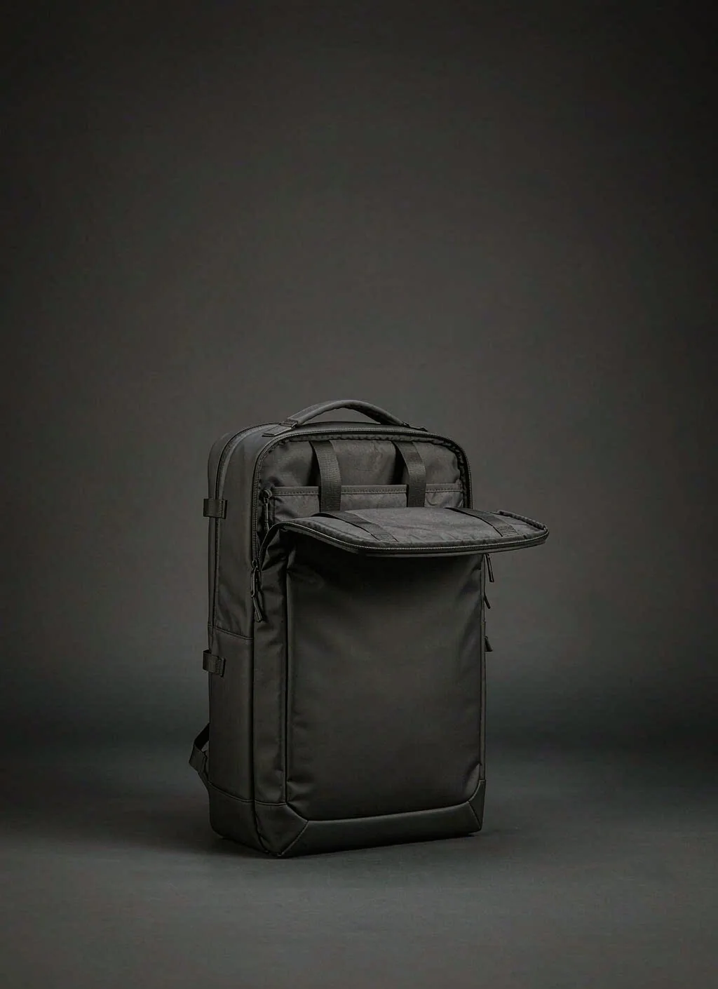
Suspending the Device Bay: Clearance, Standoff and Corner Isolation
A work carrier rarely destroys a computer through a dramatic event. Returned units usually trace to one of four contact paths: impact arriving at the device edge through the shell floor, an angular object pressing through a divider, a frame element or slider stack bearing against the lid, or the computer sliding out of its own sleeve when the body is laid flat. Each of those paths is a design decision rather than bad luck, and each is removed by altering construction rather than by piling on foam. Padding added late is the weakest response available, because closed-cell foams compress under sustained load, creep across a season and then bottom out precisely when protection is needed. Suspension works differently: no hard element touches the device anywhere along the path, so there is no localised pressure for an impact to multiply.
The mechanism begins with how the sleeve hangs. Anchoring the sleeve panel by its two upper edges to a structural seam or yoke, while its lower edge stays clear of the shell floor by a declared standoff, converts vertical movement into tension along fabric instead of compression at the device base. The standoff is not a styling line; it is the entire energy budget, and it belongs on the control drawing as a measurable dimension with tolerance so an inspector can verify it on a cut sample instead of inferring it from a photograph. Holding that standoff when the bay carries the heaviest envelope the programme declares support for is the difficult half, since height lost to creep is height that no subsequent test returns.
Drop language therefore has to be written as planning evidence, not presented as a rating. A defensible statement names the surrogate standing in for the computer, the content set installed in the body, the orientations challenged, the surface, the sequence and count, the conditioning applied beforehand, and the endpoints measured afterwards: no seam run-out at the bay, no hardware release, no closure that stops working, the surrogate within a cosmetic threshold agreed with the buyer, and continued access to every compartment. ISTA 3A has a place in the same programme, but it addresses a packed carton moving through parcel distribution rather than a body falling while worn, and presenting one result as the other is the fastest route to a claim nobody can substantiate.
| Contact path | How it forms | Construction response | Check on first article | Evidence to retain |
|---|---|---|---|---|
| Base transmission | Sleeve resting on the floor seam pushes set-down impact straight into the device edge | Hang the sleeve from upper seams with a stated standoff above the floor | Loaded vertical set-down, then measure remaining clearance | Cut-sample side view with the dimension noted on the drawing |
| Corner concentration | Body set down on one lower corner focuses energy at the device corner | Extend the corner wrap so the corner sits inside a padded volume | Corner-down sequence on a dressed sample | Orientation list plus post-sequence corner inspection |
| Divider press-through | Brick, adapter or tool pressing through one layer into the lid | Dedicated soft-walled utility bay with a compressible layer between | Heaviest declared content set installed, then external squeeze applied | Content set declaration and the squeeze review finding |
| Slider track pressure | Teeth and slider stack behind the panel the device rests against | Keep the track out of the device plane, add a garage and backing | Run the slider fully with the surrogate in place | Photograph of the track path relative to the bay |
| Frame termination | Stiffener or sheet edge printing a line across the device face | Terminate the stiffener clear of the bay, or cap it | Press along the back with the body flat and loaded | Stiffener drawing carrying a keep-clear annotation |
| Entry squeeze | Device sliding out when the body is laid flat or lifted by one strap | Deep guarded entry with a restraint tab above it | Lay fully packed, lift by one strap, then tip forward | Retention note with the surrogate reference |
| Foam creep | Height lost after sustained compression across a season | Material chosen for recovery, verified rather than assumed | Compression recovery compared before and after sustained load | Foam reference, lot and recovery record |
Leads, Chargers and Power Cells: Routing Rather Than Storage
The computer is seldom the hazard; the things carried beside it are. A mains brick, a travel adapter, a drive in a metal shell and a folding tool are the objects that appear in damage photographs, and they cause harm because a single-layer divider offers neither distance nor compressible depth between a hard corner and the lid of a computer. The governing rule is therefore positional rather than material: angular hardware belongs in a bay that never shares a single-layer wall with device storage. The second rule is that every lead needs a destination. Connectors left loose abrade lining at their corners, hook into each other, and turn a quick reach into a search, and users respond to that friction by pushing everything into one cavity, which recreates the first problem.
Routing options divide into fixed and movable. A loop bank sewn directly to a board keeps each item in one place and costs little, but it locks the set to whatever sizes were drawn and makes cleaning awkward once dust and cable debris settle into the channels. A lift-out board with elastic keepers lets a user reconfigure the set, suits mixed fleets where different teams carry different hardware, and can be issued as a spare unit that replaces rather than repairs a damaged interior. A bound pass-through between the utility bay and the device bay lets one lead run without crossing a zipper line, which protects both the lining and the closure behaviour when the body is stuffed fuller than the design intent. Whatever route is chosen, each free end needs a parking position, because unresolved connector ends cause more liner damage than any other interior element.
Where a programme wants external charging hardware fitted, treat it as component procurement rather than a sewing instruction. A port adds an opening through the face, a route for water, a snag point, an approved third-party supplier, a failure mode outside the competence of a cutting room, and after-sales responsibility that most bag programmes are not structured to carry. Internal routing plus a written instruction leaflet serves most fleets better. Power cells then take their own position: separated from the device by a soft wall, held clear of prolonged contact with the wearer, and never compressed against another hard object. Nothing about charging behaviour, heat management or cell safety belongs in a carrier specification, because those are properties of the cell and of its own compliance paperwork. Programmes laying out this layer often borrow the discipline used for dense everyday carry layouts, where each lead and each hard object is given a named position before artwork starts.
| Routing element | Effect on the user | Problem introduced when omitted | Control on the drawing | Verification |
|---|---|---|---|---|
| Loop bank on a lift-out board | Every item visible and reachable in one movement | Loose leads abrade lining and hook into one another | Keeper positions drawn to the declared connector family | Fit the full set, then shake and tip the body |
| Soft-walled utility bay | Hard objects stay together and away from the device | Corner pressure through a single divider layer | Two-layer construction with one compressible wall declared | Squeeze review with the heavy content set installed |
| Bound pass-through | One cable crosses between volumes without touching hardware | Lead trapped by a zipper when the body is full | Binding method and clearance around the opening | Run the closure repeatedly with the lead in place |
| Connector parking position | Free ends stay put instead of wandering | End corners cutting through liner over time | Parking stated per item in the kit | Inspect liner after repeated pack and unpack |
| Power cell position | Cell sits clear of the device and of body contact | Hard contact plus sustained pressure against the wearer | Separate bay with its own soft wall | Long-duration carry followed by a contact review |
| External port hardware | Charging without opening the shell | Ingress path, snag risk and an uncontrolled component | Approved component reference and its drawing | Function check plus exposure review if retained |
| Instruction leaflet | Users know what may go beside the computer | Warranty disputes over damage nobody prohibited | Leaflet controlled as part of the pack | Reviewed against the declared content set |
Flat Work, Folders and Small Stationery
Paper fails differently from electronics. It creases, corners curl, and ink runs when a shell takes water, and a creased sheet does not recover. Three conditions prevent all of that: a separator stiff enough not to roll when the body is over-packed, a position where no structural element presses a line across the pile, and a dry cavity. The last condition is the one most often ignored until returns arrive, because the two liquids most likely to be carried, a bottle and a folded umbrella, are usually placed where they can reach everything else. A lined base pocket or an external holder with genuine drainage separation solves the problem at source, whereas a resistant liner inside the same cavity merely delays the visible mark.
Position then becomes a question of what shares the wall. Putting the flat sleeve against the back panel buys dimensional stability and costs ready access; putting it against the outer face buys immediate retrieval and exposes it to whatever the body is set against. Whichever is chosen, the drawing should record what sits behind that wall, because a frame-sheet termination, a stiffener edge, a harness anchor bar tack or a slider track will each print a permanent line into folded sheets across a season of use. Fleets issued to staff who work from vehicles usually prefer front access, since withdrawing a folder while seated beats opening the body across a passenger seat, and that preference should be settled in the brief rather than discovered in use.
Small items close the loop and are where low-cost builds lose their after-sales budget. Pen loops need a lining that resists ink transfer and enough depth that a cap does not lever the binding open. Badge clips and card windows belong where they can be read without opening anything, which is simultaneously the least secure position, and the trade-off should be stated rather than denied. Nothing that leaks shares a cavity with stationery, and printed labels need checking against laminated covers, since transfer onto coated stock is a regular complaint that no amount of padding fixes. Detail organisers developed for chest rigs and compact waist pouches translate well here, particularly where a role requires many small items within arm's reach while standing.
| Class | Position that suits it | Dominant damage | Check on a dressed body | Note for the manual |
|---|---|---|---|---|
| Correspondence and reports | Flat sleeve behind a stiff separator with nothing hard across it | Crease printed by a frame termination or slider track | Press the back against a hard edge and inspect the sleeve | State the practical folder depth the pocket accepts |
| Signed contracts | Innermost dry sleeve, away from every liquid position | Water marking from a bottle or umbrella sharing the volume | Wetted carry followed by sleeve inspection | Keep liquids out of the document cavity entirely |
| Tablet or e-reader | Own suspended position, or the sleeve with a soft interlayer | Corner denting from hard objects behind the same wall | Squeeze review with the declared content set fitted | Declare which envelopes this position supports |
| Notebooks and pads | Opposite the hard-object bay, behind two layers | Board distortion from an adjacent angular item | Close fully, squeeze, then inspect the board | Oversized items alter the packed profile |
| Writing tools | Dedicated loop strip with an ink-resistant lining | Cap levering the binding, ink transfer onto lining | Load every loop and flex the panel repeatedly | Avoid loops directly over the device plane |
| Identity and access cards | External window for frequent reading, internal position for secure issue | Loss through casual access, signal picked up elsewhere | Reach the card while the body stays shut | Give the secure-issue variant its own position |
| Receipts and loose sheets | Slip pocket whose closure survives vibration | Creasing at the fold, items escaping when set down | Tip and shake test fully packed | A closed slip pocket removes most loss cases |
| Wet or damp items | Lined base pocket or external holder with drainage separation | Ingress reaching paper and electronics alike | Fill and invert, then inspect neighbouring cavities | Never share this cavity with documents |
Commute and Travel: Two Duty Cycles on a Stubbornly Single Chassis
One shell serving two duties works when the difference is published as configuration rather than left for the user to invent. Commuting is high frequency and short duration: dozens of closures a day, tight clearances at turnstiles, car doors and meeting-room furniture, a reception or screening line, coffee and a phone and a pass all reachable without stopping, and a profile slim enough that nothing gets knocked off a desk. Travel reverses most of it: fewer closure cycles but far longer wear, more mass carried farther, overhead locker constraints, uneven ground, and contents that switch from documents to clothing between morning and evening.
Those environments pull the suspension in opposing directions. Daily work rewards a slim profile, moderate padding that dries quickly, and low empty mass for short repeated carries; longer journeys reward broader shoulder contact, a load path that reaches the hip, and ventilation that still works when the body is heavily loaded. Choosing one harness for both is legitimate, provided the compromise is declared: publish the duty each configuration was validated against, the content set used, and where the suspension stops being comfortable. Volume follows the same logic. A commuter-friendly silhouette and a genuine multi-day capacity cannot both be optimal, so the usual answer is a core volume with compression that changes the profile rather than bulk that cannot be removed.
The durable solution is one core plus two kit contents rather than two bodies. The core carries the suspended bay, the document sleeve, the harness and a single internal interface, whether that is rows built at 25 mm webbing / 38 mm vertical spacing / 50 mm horizontal repeat, a loop field, or a lift-out board. One kit holds the daily organiser set; the other holds packing modules and laundry separation. One interface, two declared configurations, one spare-part inventory, and a far simpler after-sales story. Because cabin allowances vary by carrier and route, hand-luggage dimensions belong to the planning stage alongside the modular travel backpack reference material, and the drawing should quote the shell while the buyer matches those values to the routes their staff actually fly.
| Element | Daily commute weighting | Multi-day travel weighting | Requirement shared by both | Principal cost driver |
|---|---|---|---|---|
| Suspended computer bay | Carried every day, so cumulative exposure dominates | Fewer cycles but longer continuous exposure | Not negotiable in either configuration | Two-layer build and a defended standoff |
| Harness padding and load path | Moderate padding, low bulk, fast drying | Broader contact and real transfer into the hip | One declared compromise in the manual | Moulded or multi-layer construction |
| Reach for pass, phone and ticket | Continuous requirement while walking | Mostly at terminal and arrival points | Reachable without removing the body | External pocket geometry |
| Liquid position | Bottle carried daily | Longer duration against the same lining | Separated from paper and electronics | Lining material and seam treatment |
| Profile control | Slim enough for crowded vehicles | Packing efficiency over several days | One compression system for both | Buckle family and webbing routing |
| Packing modules | Rarely used | Central to the configuration | Sold as a second kit on the same interface | Additional module lines and labelling |
| Internal interface | Mostly organiser panels | Mostly packing cells | One standard documented for the whole catalogue | Control drawing and published map |
| Closure hardware | Very high cycle expectation | Moderate cycles, higher consequence of failure | Cycle expectation written into the specification | Slider family and puller management |
Discreet Exteriors Against Real Mounting Capability
Corporate buyers reject external rows for reasons that have nothing to do with load capacity. Rows read as field equipment to anyone issuing bags to client-facing staff, they catch on vehicle upholstery and reception furniture, they collect dust and resist cleaning, and a surprising number of dress and uniform policies simply forbid them. Removing the outside field costs more than most product teams expect, though, because it also removes the easiest place to hang something a user needs without opening the body, which is exactly the behaviour that makes a modular system worth specifying.
Several routes recover some of that utility, and each carries a bill. An internal slot board behind a plain face keeps full discretion and costs a step of access, requiring genuine backing or the face distorts under load. An internal loop field organises beautifully, works silently, and carries nothing heavy without gradually lifting. Rows behind a zip-through cover keep external capability while adding a zipper line across a large panel, a place water can sit, and a cover that snags unless its hardware is managed. Colour-matched slots cut into the face offer the flattest visible profile available, at the cost of switch-like tear initiation at each opening end and no possibility of repair by restitching. A removable external adapter panel, carried inside until required, gives full capability on demand and adds one more part that can be lost. A bound daisy chain tucked under a lip handles clips and cords cheaply and carries nothing substantial. Any cover variant needs its own verification, because once a cover intervenes, row load passes through cover geometry rather than straight into the panel unless the cover is tied into structure.
Two trims from one body is usually the cheapest resolution available. Hold the internal architecture, the suspended bay, the harness and the interface identical, and vary only the outer treatment: a plain-face trim for corporate issue and a mounted-face trim for crews whose work genuinely needs it. Every external arrangement that retains threading capability stays under the same control as the internal field described in the MOLLE interface reference, including 25 mm webbing, 38 mm vertical spacing and 50 mm horizontal repeat, because running two pitch standards across one catalogue guarantees some modules will not thread on some bodies. Module inventory then serves both channels while change control stays at a single interface.
| Treatment | Capability retained | Visual reading | Cost usually overlooked | Channel it suits |
|---|---|---|---|---|
| Plain face over an internal slot board | Full threading, one step slower to reach | Corporate neutral | Face distortion and added panel stiffness | Corporate issue, client-facing staff |
| Plain face over an internal loop field | Interior organisation only, no external load | Entirely neutral | Lint accumulation and long-term matting | Administrative and travel users |
| Rows behind a zip-through cover | External load kept behind an extra step | Revealed only when opened | Zipper line across the face, water retention, snag hardware | Field staff under a dress code |
| Slots cut into the face in a matching tone | Threading at a flat profile | Almost invisible when tonal | Tear initiation at each opening end, no repair route | Contemporary uniform programmes |
| Removable adapter panel carried inside | Full external capability deployed on demand | Neutral until fitted | Additional line item, loss risk, testing with rows loaded | Mixed fleets and contractor pools |
| Bound daisy chain under a lip | Clips and cords, nothing carried | Discreet | No pouch retention at all | Secondary utility touches |
| Mounted face in shell colour | Highest capability, fastest reach | Plainly technical | Cleaning difficulty and policy objections | Site crews and service technicians |
RFID, Theft Delay and Cut Claims: Where the Copy Has to Stop
Signal shielding means one thing in construction terms: a conductive layer laminated behind the panels it is declared to cover, so cards inside that enclosure experience attenuation. Three limits follow, and retail copy rarely states any of them. Coverage extends only to the lined enclosure, so cards elsewhere receive nothing; performance depends on layer continuity, meaning a crease, a needle line or a cut end can compromise it; and it says nothing whatsoever about other routes to the same data. A specification can honestly state which pockets carry the liner, cite the component reference, give the coverage area, and name the report behind the attenuation statement. It cannot honestly state that the body protects the holder.
The umbrella word theft protection collapses several unrelated devices. Lockable sliders and puller garages slow a casual opening. A cut-resistant core inside a strap delays cutting that strap, and its benefit stops where the strap meets the body. Access relocated to the back panel removes the obvious target. A loop that accepts a restraint discourages opportunistic removal from a chair or a table. None of them prevents determined action, and none should be described as if it did. The same discipline applies to resistance language written about fabric: the property belongs to a specified panel under a specified method, not to the assembled body, and replacing an absolute word with a named component plus a stated limit costs a brand nothing while removing an argument later.
The commercial reason for rigour is unsentimental. One unqualified phrase reaching marketplace copy can trigger a substantiation request from a retailer, a listing review, or an enquiry from a consumer authority, and answering any of it costs more than deleting the phrase would have. The cheapest control is a register maintained beside the tech pack, listing the proposed phrase, the component concerned, the report cited, the approved wording and the markets where each version appears. Sellers usually discover the narrower sentence is also the stronger one: a lined card enclosure tested against a named method survives contact with a buying team, while an absolute promise does not. None of this is legal advice, and final wording belongs with counsel who knows the destination rules.
| Phrase proposed | What a reader infers | Evidence required before use | Defensible replacement | Exposure if left open |
|---|---|---|---|---|
| Signal-protected | The whole body shields every card carried | Component reference, coverage area, attenuation report, revision | Card enclosure lined with an attenuating layer | Substantiation request and listing removal |
| Theft resistant | Loss is prevented rather than delayed | No product-level route exists | Lockable garage plus concealed access, as named features | Complaint from a consumer authority |
| Cut proof | Nothing cuts anywhere on the body | None available at assembly level | Resistant webbing core in the named strap | Return framed as a safety failure |
| Waterproof | Immersion survives indefinitely | Not supported by any flat-textile result | Face textile result cited, seams described separately | Leaks reported as manufacturing defects |
| Drop approved | An external authority endorsed the build | No such approval is held | Verified against a declared internal procedure | Misrepresentation allegation |
| Guaranteed for life | Replacement regardless of use or duration | Undefined scope and settlement route | Stated term, exclusions and a claim process | Warranty exposure with no boundary |
| Tactical grade | Compliance with some external standard | No such civilian standard is implied here | Described by its actual material and construction | Buyer dispute over undefined terminology |
Corporate Identification: Embroidery, Printing, Labels and Colour Splits
Identification changes the object. Direct embroidery perforates a face textile repeatedly along a fill; on a coated shell those perforations become a route for water and a line along which tearing can begin, and behind computer storage they add local thickness that presses into the lid. The response is not to prohibit embroidery but to place it: on its own panel, clear of the keep-clear zones around the bay and the suspension seams, with a backing restoring continuity wherever the construction allows it. Dense fills sitting directly over a suspended bay are the arrangement most often seen in comfort complaints that have no obvious structural cause.
Every other route has a comparable interaction. Screen inks sit on the surface and crack at folds or high-flex positions unless the ink system matches the coating underneath, and each additional ink and each additional placement carries its own set-up. Transfers adhere well on some coatings and lift on others, and their application introduces heat into panels that may already contain foam or laminate layers. Silicone and rubber patches wear extremely well and clean down easily, but add mass and local stiffness where the panel wants to roll. Woven labels on binding have to survive everything the binding itself experiences. All of these sit close to the user, which is why they matter in restricted-substance screening: coatings, inks and transfer films referenced against REACH (EC 1907/2006) are usually the layers that decide whether a colourway passes.
Colour governance runs substrate by substrate. A single nominated reference reads differently on shell fabric, webbing, binding, print, thread and hardware finish, so each is approved separately against retained chips held under one revision rather than accepted as a family. Additional shades bring additional material lots, additional machine set-ups and additional inspection time, and they change how sampling is scheduled, so settling the split at quotation is markedly cheaper than settling it once samples are on the table. Quantity follows the same reasoning: orders begin at MOQ 500, and how that floor is read across colourways and placements belongs in the quotation because print presses, embroidery machines and dyelots schedule differently. A removable badge panel is often worth the extra part, letting a corporate customer re-identify a fleet without the body being recut.
| Route | Where it survives longest | Interaction with the shell | Colour governance | Planning consequence |
|---|---|---|---|---|
| Direct embroidery on the face | Low-flex panels away from folds, loads and device pressure | Perforates coatings, stiffens locally, admits water | Thread reference matched to the shell lot | Needs a backing plan and keep-clear drawing |
| Embroidered patch applied later | Flexing entries where direct stitching would tear | Thickness added only at the application seam | Thread plus patch base approved together | Cheapest route to later re-badging |
| Screen print | Flat panels that never form a hard crease | Ink cracking where the system mismatches the coating | Ink approved against the specific substrate | Each colour and placement is its own set-up |
| Heat-applied transfer | Smooth bonded surfaces with light flex | Application heat affects foam and laminate layers | Print reference and approved application window | Unsuitable over heavier flex zones |
| Silicone or moulded patch | Entries and panels rubbed against vehicles daily | Adds mass and stiffness where a fold is wanted | Moulded part reference per shade | Tooling question and a longer component lead |
| Woven label on binding | Internal seams and identity positions | Binding flex can lift corners over time | Yarn and weave approved per lot | Legibility confirmed on the physical part |
| Removable badge panel | Any external position offered for re-identification | One extra part carried on the existing interface | Panel and print approved on both substrates | Fleet re-branding without new shells |
Laboratory Routes and Acceptance Endpoints for a Work Carrier
Begin with materials, because every later result depends on knowing exactly what was cut. ASTM D5034 provides a grab tensile route for the shell, the lining and the backing stack, useful only where the report names the substrate, coating, colour and lot rather than a generic family. ISO 12947 addresses abrasion resistance of shell and lining constructions and deserves to be run across printed and embroidered areas as well, since decoration frequently wears before the textile beneath it does. AATCC 127 measures resistance to water penetration under a hydrostatic head, and ASTM D751 covers methods relevant to coated and laminated constructions. All four are flat-specimen results. None of them sees a seam, a needle hole, a bound pass-through or a slider track, which is precisely where exposure begins on a finished body, so each one has to be followed by something run on the assembled article.
Assembly evidence then retires the risks a material certificate cannot reach. A static pull on each handle and strap with the declared content set installed finds anchorage problems that no fabric report predicts. A cyclic zipper run with the panel dressed as it will actually be carried exposes slider behaviour under real load rather than in isolation. Repeated removal and return of the surrogate checks whether the bay still guides it after wear. Cyclic threading matters wherever rows or slots remain. Conditioning followed by the internal drop procedure covers what happens after the body has been through wetting, dust exposure or thermal ageing, and ISTA 3A handles the case where the unit travels as its own parcel. Write the endpoints before anything is damaged: no crack propagation away from an anchor, no seam run-out past the agreed limit, no hardware release, no closure that stops functioning, no loss of access to any compartment, no permanent deformation that alters how the body sits.
Sampling and change control complete the loop. Final inspection at AQL 2.5, whose sampling logic comes from ISO 2859-1, can only judge what is visible on a finished unit, which places the burden for hidden construction on earlier evidence: a first-piece unit cut and photographed, in-process records after any needle or operator change, and a reference unit retained per colourway and per lot. Naming re-verification triggers inside the specification saves arguments later, because foam reference, webbing lot, hardware family, zipper make, print system and face treatment each change whole-assembly behaviour when substituted alone. EN 1811 also belongs here for metal parts in prolonged skin contact, which is exactly the condition applying to hardware pressing against shoulder and hip during long carries.
| Risk retired | Route applied | What is genuinely measured | Limit that must be stated | Endpoint recorded |
|---|---|---|---|---|
| Face splitting under concentrated load | ASTM D5034 | Grab tensile behaviour of the named lot | Says nothing about seams or anchors | Result filed against material, colour and lot |
| Surface and decoration wear | ISO 12947 | Abrasion behaviour of constructions as supplied | Flat specimen, excludes seam stacks | Endpoint reached on decorated areas too |
| Penetration through face textile | AATCC 127 | Hydrostatic resistance in millimetres of head | Excludes seams, needle holes and ports | Value plus a finished-body exposure review |
| Coating and laminate behaviour | ASTM D751 | Performance relevant to coated constructions | Does not cover folding or welding | Bond note taken after folding the part |
| Closure durability in service | Cyclic run on a dressed body | Slider and track behaviour over repetition | Belongs to that hardware family only | Cycles reached and the change observed |
| Anchorage under packed load | Static pull with declared content set | Transfer of concentrated load into the stack | Depends entirely on how it is fixtured | No deformation past the agreed limit |
| Protection in a worn fall | Declared internal procedure | Behaviour of the configured assembly | Internal planning evidence, not a rating | Surrogate state, seam state, continued access |
| Distribution in its own carton | ISTA 3A | Parcel-level sequence as shipped | Covers the shipping unit, not the worn body | Unit condition and internal presentation after |
| Metal parts against skin | EN 1811 | Release from hardware in prolonged contact | Applies to the tested article and finish | Finish reference held against the report |
Commercial Gates, Production Capacity and Export Documentation
Commercial order begins with a brief closing four questions before any drawing is produced: which device envelopes the bay accepts, what content set the body carries, which duty cycles it is validated against, and which destinations receive it. Those four answers determine everything downstream. The tech pack follows, and the interface should be frozen ahead of artwork, since relocating a row or a loop field after decoration has been laid out redoes placement, costing and sometimes harness balance together. Component approval is the gate most frequently skipped and the one that most often forces a second sampling round, because foam, webbing, hardware family, zipper make, face treatment and print system act as a set: substitute one for cost and the result the others were approved against quietly shifts.
Schedule then follows familiar gates. Sampling occupies 6–10 working days, extending to 12–15 where the construction genuinely warrants it, which a suspended bay combined with printed faces and dark-finish hardware usually does, and mass production runs 35–50 days counted from closure of approvals and inputs rather than from signature. Volume starts at MOQ 500, settlement is T/T 30/70, and the trade basis is FOB Xiamen. Any figure quoted while a sample remains under review should be read as indicative only and tied to those same terms, because it shifts with fabric selection, identification route, hardware family, kit content and test scope. Capacity context helps planners sequence launches: a 4,950 m² SGS-verified production floor running 7 production lines, 149 machines and 137 people, with output planned at 200,000 units per month. Our production team sequences these programmes against foam, hardware and decoration lead times, since those three items normally set the critical path.
Transit decides the calendar, so plan backwards from the slowest leg the programme depends on: sea freight 25–35 days for volume, air 5–8 days where urgency governs, courier 3–5 days for samples and replacement parts. Documentation is assembled as it goes rather than at the end: restricted-substance declarations referencing REACH (EC 1907/2006) for European destinations, an exposure review against California Prop 65 for the United States, CPSIA where the user population brings it into scope, OEKO-TEX Standard 100 within the limits printed on its certificate, and the metal-release result already described. ISO 9001 and BSCI describe how facilities are managed and audited; neither certifies any particular shipment, and quoting either as product evidence invites exactly the argument this page advises against. Buyers ready to move from framework into a live project can continue through the custom modular backpack programme route, which walks these same gates with the deliverables attached.
Frequently asked questions
What does a suspended computer bay actually mean in construction terms?
It means the sleeve hangs from its upper edges into the body so its lower edge stays clear of the shell floor by a declared dimension, rather than resting on a seam or a base board. Nothing hard touches the computer along the load path, so a set-down impact travels into fabric tension instead of compressing a device edge. What protects the device is the absence of contact, not the quantity of foam, which is why padding added late performs poorly after weeks of compression.
Can we publish a drop height for a tactical laptop backpack?
Publish a procedure instead of a headline number. A defensible statement names the surrogate representing the computer, the content set installed, the orientations and surface used, the sequence and conditioning applied, and the endpoints measured: no seam run-out, no hardware release, no closure failure, continued access, surrogate condition within an agreed threshold. Written that way it is a contract between engineering and inspection. A bare height implies an approval nobody holds.
How much clearance should sit between the sleeve and the shell floor?
The dimension is set by the drop procedure rather than copied from another product, and it is written on the control drawing with tolerance so an inspector can measure it on a cut sample. The important part is that it survives load: many foams lose height under sustained compression, so verify the clearance again with the heaviest declared envelope installed and after a compression recovery cycle, not only on an empty body.
Is it acceptable for a charger brick to share a compartment with the computer?
Only if two genuinely separate layers sit between them, one of which is compressible. A single-layer divider offers no distance and no give, so an angular brick pressed by external load marks lids and damages panels. Give hard objects their own soft-walled bay that never shares a single-layer wall with device storage, and state that rule in the instruction leaflet so users know what the warranty reasonably assumed.
Where should a power bank sit inside a work body?
In a position of its own, separated from the computer by a soft wall, clear of prolonged contact with the wearer, and never compressed between two hard objects. Give it a keeper so it cannot migrate into the device plane. Nothing about charging behaviour, heat or cell safety belongs in the bag specification, because those are properties of the cell and its own documentation rather than of the carrier.
Should we specify an external charging port on the face?
Treat it as component procurement, not as a sewing instruction. A port introduces an opening through the face, an ingress route, a snag point, an outside supplier and an after-sales responsibility most bag programmes are not structured to carry. Most fleets do better with internal routing plus a written leaflet, and where a port is retained it needs its own approved reference, drawing and function check alongside the standard work procedures.
How do we stop documents creasing inside a soft shell?
Three things: give the sleeve a separator stiff enough not to roll when the body is over-packed, place it where no frame termination, stiffener edge, slider track or harness bar tack presses a line across it, and keep every liquid out of that cavity. The last point is usually the real cause, since bottles and umbrellas are the most common items carried and the marks only appear after water has travelled.
Where should documents sit in a commuter-friendly configuration?
Most commuters prefer documents reachable without opening the main body, which argues for front access, while the most dimensionally stable position is against the back panel. Whichever is chosen, record what lies behind that wall on the drawing, then press a dressed sample against a hard edge and inspect the sleeve for any printed line. Make the choice in the brief rather than discovering it in use.
Can one chassis really serve daily commuting and multi-day travel?
Yes, provided the difference is published rather than left to the user. Keep a core carrying the suspended bay, document sleeve, harness and one internal interface, then sell two kits on that interface: a compact organiser set for daily use and packing modules with laundry separation for trips. Declare which duty each configuration was validated against and the content set used, because harness and volume decisions involve a real compromise either way.
What compromise works for a harness used in both duties?
Choose moderate padding that dries quickly, sufficient contact area to carry a heavier travel load, and enough adjustability that the same shell fits a jacket difference, then say plainly where comfort stops. Publishing the validated duty cycle and content set protects the brand better than claiming universal comfort, and it gives buyers something concrete to match against their own use cases.
How do we keep a low-visibility exterior without losing module capability?
Move capability inward or make it deployable. An internal slot board behind a plain face retains threading at the cost of one access step; rows behind a zip-through cover keep external load while adding a zipper line and a water trap; a removable adapter panel carried inside until needed gives full external utility with a neutral appearance. Keep all of them on the same documented interface so module inventory serves every trim.
Are slots cut into the face durable enough for daily work use?
They are suitable for discreet programmes when slot height matches strap thickness and the construction behind them is genuinely backed, but they are less forgiving than sewn rows: each opening end can initiate a tear after repeated threading, and unlike a woven field there is no repair by restitching. Qualify them by cycling a production strap repeatedly and inspecting the opening ends before any load figure is discussed.
What does a signal-shielding liner actually cover?
Only the lined enclosure it is declared for. Cards left elsewhere receive no benefit, layer continuity governs performance so a crease or needle line can compromise it, and nothing about other routes to the same data is addressed. State the pockets covered, cite the component reference and coverage area, and name the report behind the attenuation statement rather than promising that the body secures anything.
How should theft-delay features be written for retail markets?
Name the component and name the limit. Lockable sliders and concealed access delay a casual attempt; a resistant core protects the strap it is built into and stops where that strap meets the body; a restraint loop discourages opportunistic removal. Keep a register beside the tech pack mapping each phrase to its evidence and approved wording, because one unqualified sentence can trigger a substantiation request that costs more than the sentence earned.
Does embroidery damage a coated face fabric?
It perforates it, and those perforations can become both a water path and a tear-initiation line, particularly when dense fills sit directly over suspended storage. Place embroidery on its own panel, keep it out of the keep-clear zones around the bay and suspension seams, add backing where construction allows, and approve thread against the specific shell substrate rather than against a colour family.
How many colourways can one 500-piece order reasonably carry?
Settle it at quotation rather than after sampling, because every additional shade adds material lots, machine set-ups and inspection time, and each substrate reads the same nominated reference differently. Print presses, embroidery machines and dyelots all schedule on different logic, so the answer depends on route and was agreed in advance. A removable badge panel often solves re-identification more cheaply than new shells.
What lead times apply to a body with printed faces and dark-finish hardware?
Sampling occupies 6–10 working days, extending to 12–15 where the combination genuinely complicates the build, and mass production takes 35–50 days counted from closure of approvals and inputs. Plan backwards from transit: sea freight 25–35 days, air 5–8 days, courier 3–5 days for samples. Terms are MOQ 500, T/T 30/70 and FOB Xiamen, with figures quoted during sampling treated as indicative only.
Which documents should accompany a volume shipment?
Ask for restricted-substance declarations referencing REACH (EC 1907/2006), an exposure review against California Prop 65 for the United States, CPSIA where the user population brings it into scope, OEKO-TEX Standard 100 within the limits printed on its certificate, and metal-release evidence such as EN 1811 for hardware touching skin. Remember that ISO 9001 and BSCI describe management systems, not the conformity of any individual shipment.