Home › Field notes › Tech Integration in Modular Backpacks: Power, Cable and Drop Gates
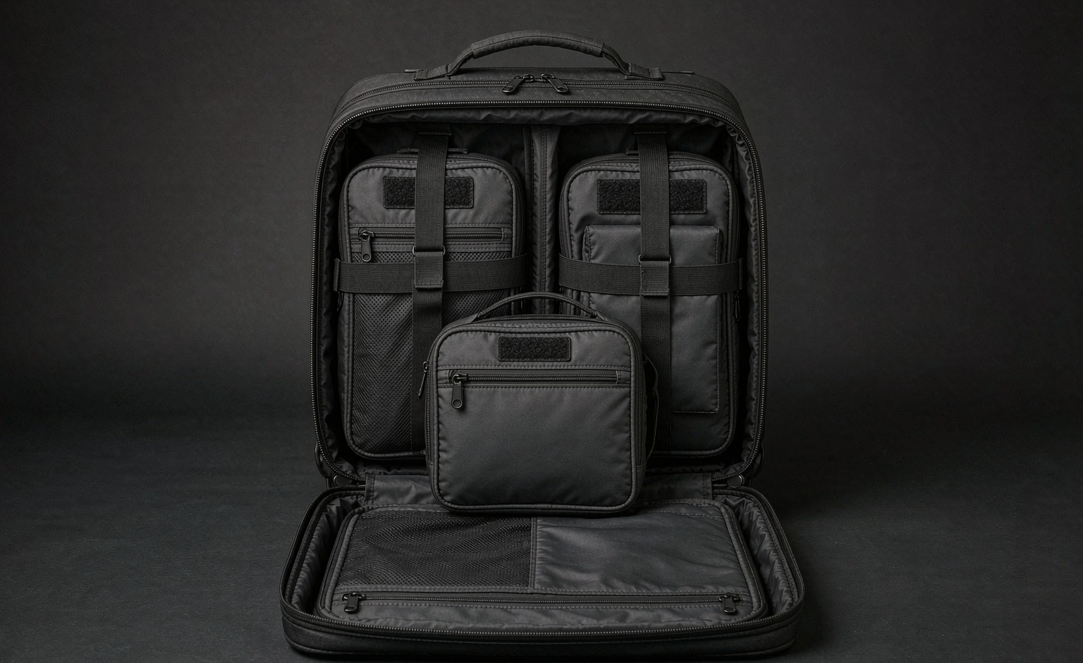
Tech integration on a modular backpack succeeds or fails on three measurable details: the tightest bend a cable is asked to make, the way a lithium cell is carried and documented for transport, and whether the device bay actually protects corners in a drop rather than merely padding them. Everything else in the category - hub count, port type, lighting - is detail that follows those three. Written as a specification line with a closing test, each becomes checkable before tooling: a minimum bend radius with a flex-cycle count, an IATA-conformant carry method for spare cells, and a corner drop with a stated height and a stated outcome. Commercial planning is unchanged by the electronics and runs from MOQ 500 per reference, sampling in 6-10 working days and mass production across 35-50 days, released at AQL 2.5. The sections below move from power through cabling to bay geometry, then finish with the acceptance gates that decide whether a built sample ships.
What tech integration actually adds to a specification
Adding technology to a carried product changes the specification in four places, and only one of them is the electronics. The first is structure: a device bay, a cable path and a power pocket all consume volume and add mass that the harness has to carry. The second is thermal behaviour, because a closed compartment holding a charging cell is a small insulated box. The third is serviceability, because a cable or a hub will fail before the shell does and has to be replaceable. The fourth is documentation, because anything containing a lithium cell travels under transport rules that apply to the finished article and not only to the component.
The common specification error is writing "with USB charging port" and treating the rest as a sewing detail. That line leaves undefined the cable gauge, the bend radius at the two ends of the run, the retention method along the run, the port's own ingress behaviour, and who replaces the harness when it fails. A modular platform makes each of those answerable separately, which is the real reason to put technology into a modular chassis rather than into a fixed one.
Buyers should also decide early whether the electronics are supplied, specified or merely accommodated. Accommodating is the low-risk route: the bag provides geometry, routing and retention, and the user supplies the device. Specifying goes further and makes the brand responsible for electrical safety documentation. Supplying a cell is the highest burden of the three and pulls the programme into transport classification, cell certification and a stricter incoming-inspection regime. Most programmes that start optimistic end up in the middle category, and it is worth deciding that before sampling rather than after a compliance question is raised.
Interface discipline keeps the electronics from locking the platform. Where a power module attaches through the same 25 mm webbing lattice used by every other pouch, at 38 mm vertical spacing and 50 mm horizontal repeat, a later generation of battery can be swapped in without redesigning the chassis. A proprietary dock does the opposite and converts a two-year product into a one-cycle product.
Selection rule: Selection rule: Add a power bay only where the duty profile includes a device that must arrive charged, and specify the bay by clearance, cable route and strain relief rather than by the presence of a port, since a bay adds cost to every one of the 500 units in the opening run.
Power: cell transport rules and the design consequences
Any lithium cell in a carried product is subject to transport rules, and IATA provisions govern air carriage for both installed and spare cells. The design consequences are concrete. A spare power bank carried in a bag is treated differently from one that is built into the article, and the distinction turns on whether it is removable without tools. A removable cell in a pouch is a spare cell in transit; a cell wired into the chassis and not user-removable is an installed cell, which changes the documentation set rather than removing the obligation.
The second consequence is that the user-facing marking has to be honest about capacity. Watt-hour rating is the figure transport rules use, and it is derived from the nameplate voltage and ampere-hour capacity rather than from the marketing mAh figure alone. A specification that fixes the cell by physical size but not by rated energy leaves the programme exposed when a purchasing change quietly substitutes a higher-energy cell into the same pocket.
Third, terminals have to be protected against short circuit in transit. A loose cell in a pocket with a bunch of keys is a known hazard, and the design response is a dedicated sleeve or a recessed connector rather than an open pouch. That is a two-dollar solution to a problem that otherwise closes markets, and it belongs in the first sample rather than in a revision.
The practical programme decision is therefore to specify the power element as a removable module with a protected terminal, a documented watt-hour ceiling, and a marking panel inside the pocket. That keeps the chassis sellable into markets the brand has not yet entered, and it means a cell recall does not become a bag recall. Our production team builds the pocket and the cable path to a drawing and treats the cell itself as a bought-in component with its own certificate file, which is the cleanest split of responsibility for a brand that does not want to become an electronics supplier.
Bottom line: Bottom line: Design for the cell transport rules that apply to the buyer's own market, and make the power source removable, because a fixed cell turns a bag into a regulated article at the checkpoint and can strand air freight booked at 5-8 days.
Cable routing: bend radius, strain relief and failure modes
Cables fail from repeated bending at a fixed point, not from tension along the run. The specification line that prevents it is a minimum bend radius, typically expressed as a multiple of the cable's outer diameter, plus a stated count of flex cycles at that radius. Where a cable exits a pocket and turns through ninety degrees into a chassis, the corner is the failure point, and the fix is a moulded or stitched guide that spreads the bend over a longer arc rather than a sharper one.
Strain relief is the second requirement and the one most often skipped. A cable that terminates in a connector must have its load taken by the structure, not by the solder joint; in practice that means a clamp or a stitched anchor within a short distance of each termination. Without it, a user tugging a device out of a bay transmits the pull straight into the weakest joint in the assembly.
Service loops are the third element. A short length of slack at each end allows a module to be detached and reattached without pulling on the run, and it allows a technician to replace a harness without unpicking the whole lining. The loop has to be retained, though: unrestrained slack inside a bag migrates, tangles and eventually finds a zipper.
Finally, the run has to survive the bag's own duty cycle, which includes abrasion against the lining, compression under load, and laundering or wipe-down. Testing a cable route as part of the finished article rather than as a component is what catches the real failure, because a harness that passes a bench flex test can still be crushed where it crosses a seam allowance. Verification belongs in the sampling window, which is 6-10 working days for a conventional harness and 12-15 where a moulded guide or a welded pass-through is required.
Device bay geometry: clearance, suspended floor and corner protection
A device bay is a dimensional problem before it is a padding problem. Published device dimensions are external and exclude a case, so the bay has to be sized over the cased device, with clearance on all four sides so the device can be inserted without forcing and removed without prising. Forcing is the failure mode that breaks both zips and device screens.
The floor of the bay matters more than the padding. A suspended floor, raised a defined distance above the base of the bag with an air gap beneath, converts a drop onto the bottom corner into a deflection rather than a direct impact. The specification should state the gap, the foam density or the structured panel that maintains it, and the load at which the gap collapses - because a gap that closes under a fully packed bag provides no protection at the moment it is needed.
Corner protection is where the drop energy actually goes. A drop onto a corner concentrates the load into a small area, and a bay with generous face padding but unprotected corners fails a corner drop while passing a flat one. Both should be specified: flat drop and corner drop, at a stated height onto a stated surface, with a stated outcome such as no visible damage and no loss of function.
ISTA 3A provides a recognised parcel-drop and handling sequence that buyers use when the bag is shipped filled to an end customer, and MIL-STD-810 is referenced in field-oriented programmes as a shock and environmental method rather than as a certification. Neither is a substitute for stating the height, the surface and the outcome in the buyer's own document. What closes a disagreement is a written test with a written pass criterion, agreed before the first sample is cut.
Verdict: Verdict: Give the device a suspended floor with clearance at every corner, state the maximum device size the bay accepts in millimetres, and confirm the case-fit allowance on a 6-10 working day sample before the chassis drawing is frozen.
Acceptance checks that close a tech-integrated sample
| Check | Method | Pass reading | Corrective action |
|---|---|---|---|
| Insertion clearance | Cased reference device, insertion and removal cycle | Inserts and removes without forcing, 25 cycles | Add clearance on the two short sides |
| Corner drop | Loaded bag dropped onto the bay corner | Device undamaged and functional at stated height | Increase suspended-floor gap or stiffen corner |
| Cable flex | Flex at the tightest bend in the run | Continuity retained through the stated cycle count | Extend the bend arc with a guide |
| Termination pull | Static pull on the connector after strain relief | Load taken by the clamp, no movement at the joint | Move the anchor closer to the termination |
| Thermal soak | Charge cycle in a closed bay at elevated ambient | Surface temperature below the stated ceiling | Vent the bay or reduce charge current |
Thermal and electromagnetic behaviour inside a closed bay
A charging cell inside a closed compartment is a heat source in an insulated box, and the temperature rise is a function of charge current, ambient temperature and the insulating value of the surrounding panels. The specification response is a ceiling on surface temperature reached during a defined charge cycle at a defined ambient, and a test that runs the actual cycle rather than a spot reading taken after five minutes. Charge behaviour at the top of the ambient range is where the difference appears.
Ventilation has to be designed rather than hoped for. A convected path through the harness channel, or a vented panel placed where a user's back does not seal it, moves enough air to change the result materially. A mesh panel placed against the wearer's back is not ventilation; it is decoration, because it is blocked when the bag is worn, which is exactly when charging happens.
Electromagnetic behaviour is usually benign but occasionally decisive. A hub or a charging board sitting against a radio or a navigation antenna can raise the noise floor enough to degrade reception, and the effect is position-dependent, so it is discovered late if it is not looked for. The control is physical separation: place the electronics in a compartment away from the device bay's antenna edge, and keep cable runs short and away from that edge.
Where a programme includes a locator or a radio module, the battery replacement cycle becomes a specification item too. A sealed module that cannot have its cell replaced converts the whole bag into consumable electronics, which is the opposite of what a modular platform is supposed to achieve. An accessible module on the standard webbing lattice shared across the platform avoids that trap and keeps the electronic element upgradeable independently of the shell.
Takeaway: Takeaway: State an enclosure rating for the bay using the code set out in IEC 60529, and test the closed bay for heat build-up under charge, because a sealed pocket holding a power bank is a thermal problem before becoming a convenience, and the bay should be re-checked once sampling in 6-10 working days has produced a working prototype.
Integration routes compared by serviceability and risk
| Route | Service access | Added mass | Risk carried |
|---|---|---|---|
| Fixed internal harness | Lining unpick, technician only | Lowest | Whole bag out of service on cable fault |
| Removable caddy module | User, through the webbing lattice | Moderate | Connector wear at the docking face |
| Pass-through port only | User, no internal element | Lowest | Ingress at the port if not shuttered |
| Strap-on external bank | User, immediate | Carried on the harness | Snag and loss if retention is weak |
Revision strategy for a platform that outlives its electronics
Electronics turn over faster than patterns, and a chassis designed around a specific device shape is obsolete the moment that device is superseded. The durable alternative is to design to a dimension band and a retention method rather than to a model: state the largest cased device the bay must accept, the smallest it must still retain securely, and the retention mechanism that bridges the gap. A pocket sized that way survives two or three device generations without a pattern change.
Cable and connector standards move more slowly than devices but still move. Designing the harness as a replaceable sub-assembly, retained by accessible fixings rather than buried under a lining, converts a connector change from a re-cut into a component swap. That is the single decision that most affects the serviceable life of a powered platform.
Documentation should follow the same logic. A file that records the rated energy ceiling, the connector type and the routing geometry allows a substitution to be assessed without rebuilding the whole compliance case, whereas a file that records only a part number forces the case to be reopened each time.
Finally, the commercial case for modularity rests on this revision behaviour. A brand that can refresh the power element without touching the shell refreshes a product line at component cost rather than at tooling cost, and that difference is usually what pays for the additional engineering the modular interface required in the first place.
Programme gates from sample to shipment
The gate sequence for a tech-integrated reference follows the standard shape with the electronics inserted as additional items at each gate. At sample approval, the extra items are the cable flex result, the insertion-clearance cycle and the thermal-soak reading; those three are cheap to fix on a sample and expensive to fix after tooling. At in-line inspection, the extra item is connector orientation and strain-relief placement, because those are assembly errors rather than design errors and they cluster at the start of a run.
At final release, inspection runs at AQL 2.5 under ISO 2859-1 sampling principles, with the electronics treated as a distinct defect class rather than lumped with sewing defects. A bag with a perfect shell and an intermittent connector is a functional reject, and mixing the two classes hides it in the statistics. Separating the classes makes the failure visible in the data and points at the station that caused it.
Timing follows the standard calendar: sampling in 6-10 working days, extending to 12-15 where a moulded cable guide, a welded pass-through or a new hub is involved; mass production across 35-50 days, with the upper end applying where a bought-in electronic component has its own lead time. Five hundred pieces is the floor for any single reference, and where the power element is held as its own stock unit it should be ordered against that same quantity so shell and electronics arrive together rather than in two shipments with two clearance events.
Two further cost lines sit beside the unit price. Screens or dies for a logo fall between USD 300-2,500 depending on the process, and the USD 50-150 charged to develop a sample is credited back once the order is placed; both are indicative only and quoted FOB Xiamen. Freight deserves an early decision wherever a cell is present, because ocean transit of 25-35 days and air transit of 5-8 days carry different documentation obligations for lithium content, while express carriers at 3-5 days commonly refuse cells outright and should never be assumed for a powered sample.
Behind the schedule sit seven lines and 149 machines with quoted monthly output of 200,000 units. That parallelism is what lets a powered sub-assembly for a work-oriented chassis be built on its own line and married to the shell at final assembly rather than lengthening the critical path, and it is the reason a chassis with a harness can be quoted on the same calendar as one without.
A closing note on revision discipline. Electronics change faster than patterns, so the specification should fix the pocket geometry, the retention method and the interface, while leaving the device itself open to substitution. A design that depends on one particular power bank shape is obsolete the moment that model is discontinued, whereas a pocket sized to a dimension band with a retention strap stays usable across several generations of cells.
Spec rule: Spec rule: Gate the programme on a 6-10 working day sample, a drop and vibration sequence on the packed carton, and AQL 2.5 release on the finished lot before the 35-50 day production window is booked.
Frequently asked questions
What is the most common cause of failure in a charging harness?
Repeated bending at a fixed point, usually where the cable turns ninety degrees out of a pocket. A minimum bend radius expressed as a multiple of cable diameter, plus a stated flex-cycle count, prevents it.
How should a spare power bank be carried to satisfy transport rules?
Protected against short circuit, in a dedicated sleeve or recessed connector, with terminals not exposed to loose metal objects. IATA provisions treat a removable cell differently from one installed in the article.
Why is corner drop specified separately from a flat drop?
Corner impact concentrates the load into a small area, so a bay with generous face padding can still fail. Both orientations should be written with a height, a surface and a pass outcome.
What clearance should a device bay allow over a cased device?
Enough that the device inserts and removes without forcing across repeated cycles, on all four sides. Forcing is what breaks zips and device screens; typical verification runs 25 insertion cycles.
Does a suspended floor actually protect a laptop?
Yes, when the gap is maintained under packed load. An air gap converts bottom-corner impact into deflection, but a gap that collapses under a full load offers no protection at the moment it is needed.
How is heat managed when charging inside a closed compartment?
Set a surface-temperature ceiling for a defined charge cycle at a defined ambient, then design a convected path that is not blocked when the bag is worn. A mesh panel against the back is not ventilation.
Should the electronics be a user-replaceable module?
Where possible yes. A sealed module turns the bag into consumable electronics, while a module on the standard 25 mm webbing lattice can be upgraded without redesigning the chassis.
What does ISTA 3A contribute to a backpack specification?
It provides a recognised parcel-handling and drop sequence used when the product ships filled to an end customer. It complements, and does not replace, a written drop height, surface and outcome in the buyer's own document.
How are electronic defects counted during release inspection?
As a distinct class, separate from sewing and finishing defects, at AQL 2.5. An intermittent connector is a functional reject and disappears if it is averaged in with cosmetic classes.
How long does sampling take for a powered reference?
6-10 working days for a conventional harness, extending to 12-15 where a moulded guide, a welded pass-through or a new hub is involved. The extra time is usually component lead time.
What is the minimum order quantity for a tech-integrated chassis?
MOQ 500 per reference. Where the power module is a separate stock unit it should be ordered against the same 500 so the two elements arrive together, quoted indicative only, FOB Xiamen.
Can a powered sample ship by courier?
Usually not, because cells are restricted on courier services. Plan sea at 25-35 days or air at 5-8 days for anything containing a lithium cell, and keep cell documentation with the shipment.
What bend radius should be written on a harness drawing?
Express it as a multiple of the cable's outer diameter and pair it with a flex-cycle count at that radius. A figure without a cycle count cannot be verified, and a corner guide is usually what brings the bend inside the limit.
Why should the power element be removable rather than built in?
Removability keeps the chassis sellable into markets not yet entered and means a cell problem stays a cell problem instead of becoming a bag recall. It also lets a later generation of battery drop into the same pocket.
Should a brand supply the cell or only accommodate it?
Accommodating is the low-burden route: the bag supplies geometry, routing and retention, and the user supplies the device. Supplying a cell pulls the programme into transport classification and cell certification.