Home › Field notes › What Is a Detachable Backpack Module? Definition and Load Budget
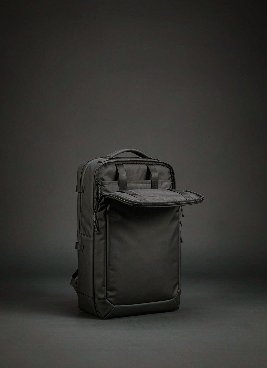
A detachable backpack module is a standalone carry unit that holds its own shape, seals with its own closure and carries its rated contents while separated from the chassis, and that a wearer can take off the chassis by hand without any tool. Four numbers decide whether such a unit works in production: the footprint it claims on a lattice of 25 mm tape pitched 38 mm row-to-row on a 50 mm column repeat, the number of anchors carrying load back into the host panel, the re-attachment count the joint survives, and the mass ceiling the chassis accepts before harness geometry needs to change. Commercial mechanics run at MOQ 500 per reference, sampling across 6-10 working days, bulk sewing over 35-50 days and release inspection at AQL 2.5 against ISO 2859-1 sampling principles. The description stays inside civilian load carriage - hand tools, meters, cables, first aid, camera bodies, hydration - and deliberately excludes weapon retention, ballistic panels and any military specification claim.
What the word module commits you to in writing
A carry item earns the name only when three properties hold at the same time. It encloses volume on its own; it carries its rated contents while detached; and the wearer can separate it from the host panel by hand. A sewn-on side pocket fails the third test. A soft organiser fails the second, because it collapses into a cloth heap the moment it leaves the shell. A holster riveted permanently to a belt fails too, even though it holds its shape perfectly.
The distinction is not pedantry. A genuine unit normally carries its own stock code, its own pattern set, its own bill of materials, its own sample round, its own carton quantity and - in most catalogues - its own retail price when it is sold apart from the chassis. Every one of those is a cost line that a plain sewn pocket does not carry, and a costing drawn up on the assumption that it is "just a pocket" will be wrong before the first sample is cut.
Duty of care changes as well. A unit that leaves the chassis meets conditions the chassis never sees: a wet workshop floor, a gravel tailgate, the footwell of a service van, a security tray at an airport. Its base therefore needs a abrasion and puncture specification of its own rather than inheriting whatever the host shell happens to be made of, and its closure needs to survive being operated one-handed while the unit rests on a hard surface.
Scope boundaries belong in the same paragraph as the definition. Civilian programmes cover tools, instruments, hydration, first aid kits, camera bodies and personal items. This text sets aside weapon carriage, ballistic protection and any claim of military certification, and no wording elsewhere in the document should imply otherwise.
Spec rule: Put three measurable promises into the technical file - tool-free removal inside the stated number of seconds, a standalone load rating stated in kilograms, and a closure that opens and shuts while the unit lies off the chassis - and treat any candidate failing one promise as a pocket rather than a module.
Six clauses a module-to-chassis interface contract has to state
An interface contract is the short written agreement between the designer of the chassis and whoever designs the unit that mounts on it. It does not describe the shape inside the unit; it describes only what crosses the boundary, and it exists so that two parties who never meet can produce parts that fit on the first try.
| Clause | What it fixes | Signed off by | Symptom when blank |
|---|---|---|---|
| Mating standard and pitch | Tape width, row pitch, column repeat, tolerance per pitch | Chassis engineering | Prototype fits, production goods rock |
| Footprint, rows by columns | Height and width claimed on the host panel | Unit designer | Unit cannot be centred on a narrower panel |
| Load path and anchor count | Where force enters the chassis and through how many fixings | Both parties jointly | Tape tears at the top row only |
| Detach and refit count | Cycles the joint must survive with stated strength retention | Unit designer | Straps creep loose after a season |
| Mass ceiling with contents | Highest permissible filled weight | Chassis engineering | Harness pulls away from the wearer's back |
| Revision identity | Code and its permanent location on the part | Quality function | Two incompatible generations ship in one carton |
Each clause should be written as a sentence with a number in it, not as a sketch reference. "Webbing standard" is not a clause; "25 mm tape woven through rows pitched 38 mm apart, minimum three anchors, 100 % strength retention after 250 refit cycles" is, and it can be checked by two people standing on opposite sides of a bench with a tape measure.
Revision identity is the clause most often skipped and the one that costs most later. Once a second generation of the unit reaches the market, retailers hold both versions, end users mix them, and complaints arrive that cannot be reproduced because nobody knows which generation is being discussed. A woven label carrying a generation code inside the unit costs almost nothing and closes that gap permanently.
Selection rule: Accept a module drawing into a programme only when all six clauses carry a number and an owner, and reject it for rework if footprint, anchor count or detach cycles appear as notes on a sketch instead of values in a table.
Footprint arithmetic on the host lattice
Footprint arithmetic is where most first programs lose time. Rows of tape sit 38 mm apart vertically, the tape itself is 25 mm wide, and the column pattern repeats every 50 mm across the panel. From those three figures everything else follows, and none of them is negotiable if third-party items are expected to fit.
Height comes first. A unit that weaves through n rows occupies roughly (n - 1) times 38 mm plus the 25 mm tape width, so a three-row unit claims about 101 mm and a four-row unit about 139 mm. Width follows the same logic on the horizontal repeat: m channels occupy about (m - 1) times 50 mm plus a tape width, giving roughly 125 mm for three channels and 175 mm for four. Those figures are the places the eye lands when checking a drawing; they are also the figures that quietly disagree with a pattern piece cut from a slightly different assumption.
Tolerance then has to be split in two, and this is the part drawings usually miss. A per-pitch tolerance of 1 mm keeps each individual row honest, but six rows stacked under that tolerance can accumulate 6 mm of drift, which is enough to make the last row unusable. Write both figures: a permitted deviation per pitch and a maximum cumulative deviation across the whole column of rows.
Verification is cheap when it uses production materials. A go gauge cut from the same tape lot that will run on the order - not from a sample card - catches drift while the sewing line can still be corrected. Checking once per shift at the attaching station costs minutes; discovering it during release inspection costs the shipment.
Odd footprints create their own trap. A unit claiming five channels cannot be centred on panels that offer only even counts, so it hangs off one edge and pulls the load sideways. Standardising a house range on two, three, four and six channels keeps every piece centred on every panel in the family.
Takeaway: Compute every footprint from 38 mm rows, 25 mm tape and a 50 mm column repeat, publish both per-pitch and cumulative tolerances, and restrict the range to even channel counts so nothing in the family is forced to hang off an edge.
Capacity is not additive: budgeting litres across a set
Litre figures do not add up across a chassis and its units, and the reason is physical rather than accounting. A unit mounted inside the shell displaces usable space one-for-one and then some, because rigid corners leave pockets of air that nobody can fill. A unit mounted outside the shell adds genuine volume but adds depth behind the wearer's back plane, which is the dimension with the least room to spend in a crowd, a doorway or an aircraft aisle.
| Chassis band | Recommended internal allocation | Recommended external allocation | Largest sensible unit count |
|---|---|---|---|
| 20-25 L day chassis | 60-70 % of stated volume | 3-5 L across one or two units | Two |
| 26-35 L working chassis | 55-65 % of stated volume | 6-10 L across two or three units | Three |
| 36-45 L travel chassis | 50-60 % of stated volume | 10-16 L across three or four units | Four |
Density of contents decides which side of that split an item belongs on. Dense objects - batteries, hand tools, spares in metal cases, glass - belong inside and low, close to the spine. Bulky low-density objects - gloves, a shell layer, coiled cable, a packed lunch - belong outside, where added depth costs little and the mass penalty stays small.
Access frequency matters as much as mass. Something needed twenty times a day should not be buried behind two layers of internals, even though that is where it carries best. Very often the honest resolution is a compromise position: an external unit for items needed constantly, kept deliberately light so that the convenience does not turn into a balance problem.
Packing list arithmetic then finishes the job. Write the list of items the user must carry, assign each one to inside or outside, sum the two columns, and compare against the allocation above. Where the outside column overflows, the answer is a bigger unit rather than a fourth attachment point, because each extra fixing adds more in weight and sewing time than it returns in usable volume.
Bottom line: Allocate internal units to dense items carried low and close to the spine, reserve external volume for bulky low-density items, and treat any proposal needing more than four attachments on a chassis below 45 L as a sign the base volume is wrong rather than the interface.
Mass budget and the point where geometry stops helping
Two masses matter and programmes routinely confuse them. Empty mass is what the unit contributes before anything is put in it - shell fabric, lining, stiffener, foam, binding, slider hardware and labels - and for a mid-size item this commonly lands between 180 g and 350 g depending on how much structure the designer insists on. Content mass is everything else, and it is usually two to four times larger.
The penalty hides in the empty figure. Four modules at 300 g each add 1.2 kg before a single tool is loaded, and that number comes straight out of the payload the chassis was rated for. The cheapest single saving available in most programmes is therefore not lighter fabric but fewer interface features: every additional panel of stiffener, every second slider, every decorative binding that exists for appearance rather than containment.
Position drives comfort more than total figure does. Load placed behind the back plane acts through a lever arm measured from the spine, and the moment that the harness has to resist is mass multiplied by that distance. A 1 kg item carried 200 mm from the spine asks the shoulders for the same corrective effort as roughly 2 kg carried half as far, which is why a builder's level belongs against the spine and a rolled jacket belongs in an outer unit.
Harness design sets the ceiling. Straps, yoke and lumbar panel are dimensioned around a total figure chosen early; once filled configuration exceeds it by a meaningful margin, the geometry stops correcting anything and strain simply moves into the wearer's shoulders and lower back. The honest response is either to re-specify the harness or to reduce the number of attachments sold with the chassis, and in most civilian programmes the second is both cheaper and quicker.
Verdict: Budget empty mass first and subtract it from the rated payload before counting contents, then position every item so that dense loads stay within a short distance of the spine, because moving a kilogram rearward costs more comfort than adding it.
Attachment families compared: what each one trades away
Five families cover nearly everything offered to civilian buyers, and each one buys convenience with something else. Choosing between them should be a written decision against numbers rather than a preference expressed late in sampling, because the choice drives tooling, sewing minutes and the failure pattern users will report.
| Family | Holding under load along the rows | Behaviour when peeled | Refit cycles before service | Added profile | Cost impact |
|---|---|---|---|---|---|
| Hook-and-loop backing alone | Moderate, falls away with contamination | Weak; lifts from an edge | Very many, with slow decline | Flat, 3-5 mm | Lowest |
| Tape channel weave with strap | Strong, limited by bar-tack strength | Strong; load spreads across rows | Several hundred before tape wear | 6-9 mm | Moderate |
| Rigid polymer clip through tape | Strongest in this list | Very strong once seated | Hundreds, clip rarely fails | 8-12 mm | Moderate plus tooling |
| Rail and slider dock | Strong in two axes | Strong; positive engagement | Strong until slider wear appears | 10-14 mm | Highest |
| Magnet-assisted dock | Good sideways, weak in direct pull | Poor; separates by design | Very many, magnets stable | 7-11 mm | High |
Failure patterns differ as much as strengths do. Back-and-forth rubbing-fatigue appears where a unit rides against a seat back for hours; the first symptom is usually frayed hook tape rather than popped stitches. Contamination is specific to the hook-and-loop route: lint, sawdust and pet hair accumulate in the hook face, engagement depth falls, and the unit begins to walk under vibration. Panel distortion is the quiet one, where a lightweight host panel flexes under empty units and every attachment point starts to flap.
Verification should follow the same three behaviours rather than a single pull figure. Measure retention under steady load along the rows, then under a peeling load applied at one corner, then after a stated count of refit cycles. Testing to ASTM D5034 gives the tensile reference for the tape and seam combination, and a rub-colour check to AATCC 8 covers hook tape that contacts clothing.
Judgement: Specify a tape channel weave with at least three anchors wherever the unit will carry more than 1.5 kg or will be removed fewer than 300 times in service, and reserve hook-and-loop-only backs for flat, light items that prioritise a low profile over ultimate retention.
Programme resources, gate sequence and who runs the floor
The commercial calendar for a detachable unit is not the same as for a plain bag, because the unit and its host have to be sampled together and then separately. Sampling spans 6-10 working days where the shell is conventional, extending to 12-15 where a moulded dock, a welded seam or a new stiffener construction enters the drawing; the extra days are almost always spent waiting for material rather than for sewing minutes.
Gate sequence stays fixed. A development sample establishes the geometry, then a pre-production sample is cut from confirmed materials on the line that will run the order, then in-line checks watch seam construction and rail alignment, then final release runs at AQL 2.5 with the classification customary under ISO 2859-1 - critical nil, major 2.5 and minor 4.0 defects treated as separate classes rather than averaged into one figure.
Our production team coordinates this through a 4,950 m² SGS-verified production floor staffed by 137 people across 7 production lines with 149 machines, at a monthly throughput around 200,000 units; the founder has worked in bag production since 2004 and the company was established in 2014. Programme capacity is allocated per reference at MOQ 500, and bulk spans 35-50 days depending on how much bought-in hardware has its own lead time.
Settlement and freight follow predictable shapes. Quotations are indicative only and quoted FOB Xiamen on payment terms of T/T 30/70, with a response typically inside 24-48 hours of a complete brief. A sample carries a development charge of USD 50-150, credited back against the order, while screens, dies or moulds sit between USD 300-2,500. Transit then runs 25-35 days by sea, 5-8 days by air or 3-5 days by courier, and consolidation planning starts to matter once volume reaches 20GP at roughly 28 CBM or 40HQ at roughly 68 CBM.
Spec rule: Freeze the interface drawing at pre-production rather than at development approval, because the unit and the chassis change together and re-cutting one without the other is the usual origin of a second generation that silently stops fitting.
Writing the interface down so another line can reproduce it
The final test of an interface contract is whether a second production source could build a mating unit from documents alone. That requires a drawing with a fixed datum, tolerances stated numerically, an explicitly listed set of accepted equivalents for tape, hardware and thread, and a retained reference physical unit to compare against.
Re-qualification triggers deserve their own paragraph, because nearly every drift in this category enters through a substitution nobody considered material. Changing tape supplier changes stiffness and therefore how easily a strap threads; changing hardware plating changes dimensions slightly; changing binding changes how a unit sits against the host panel. Each should be written down as a trigger that pulls verification forward rather than waiting for the next scheduled round.
Practical linkage with the rest of the range also belongs in the file. Where the unit mounts on the same lattice used across a webbing standard shared by every panel in the family, a single gauge and a single drawing serve the whole programme, which is exactly why standardising pitch early saves more money than any single material decision later.
Where a programme plans its own shell rather than accepting an existing one, the custom modular backpack development route forces the same questions earlier - host panel size, row count and column repeat are fixed before styling begins, and a note in the file should record which chassis sizes each unit must centre on. Buyers assembling an entire configuration can also cross-check volumes against the modular chassis reference before committing to a full first order.
The set touches several adjacent topics that reward separate reading: the full walk-through of unit families, cost behaviour and service life is covered in our longer guide to detachable backpack modules for civilian programmes, which complements this page rather than repeating it.
Frequently asked questions
What exactly counts as a detachable backpack module?
A unit that encloses volume with its own shell, keeps working while off the chassis, and can be separated by hand without tools. A sewn pocket fails because it cannot leave; a soft organiser fails because it collapses alone. Each of the three tests should appear in your technical file with a numeric target attached.
- Own structure and closure
- Standalone load rating
- Tool-free removal
How many rows and columns should a module claim on the host panel?
Footprint follows the lattice: rows 38 mm apart, tape 25 mm wide, columns repeating every 50 mm. Standardise on two, three, four or six channels so every unit centres on every panel in the range, and publish both per-pitch and cumulative tolerance figures.
Why do litre claims fail to add up between chassis and modules?
An internal unit displaces usable space by more than its nominal volume because rigid corners leave unfillable air. An external unit adds real volume but spends depth behind the spine, which is the scarcest dimension in a crowd or an aisle. Allocate by density, not by nominal litre figures.
What is a sensible empty mass target for a mid-size module?
Budget 180-350 g of shell, lining, stiffener, binding and hardware before contents, depending on how much structure the design carries. Four units then cost 1.2 kg of rated payload before anything is loaded into them, so removing decorative features usually saves more than changing fabric.
How many anchors are enough on a tape channel weave?
Three is the working minimum for anything carrying serious load, spreading force across three rows rather than concentrating it at the top. More anchors add sewing minutes and tape bulk without much return once the load is already distributed.
What fails first on a hook-and-loop backed module?
Contamination before anything else: lint, dust and hair pack into the hook face, engagement depth drops and the unit starts walking under vibration. Fraying of the loop face follows, and both are slowed by a closure wrap or cover when the face is not in use.
Which test method covers the webbing and seam combination?
ASTM D5034 supplies the tensile and elongation reference used to compare tape and seam candidates, while ASTM D3884 or ISO 12947 supply abrasion cycles. Colour transfer onto clothing is checked separately under AATCC 8.
What release inspection level applies to a module order?
Release runs at AQL 2.5 sampled on ISO 2859-1 principles, with critical defects at nil, major at 2.5 and minor at 4.0 kept as separate classes. Merging cosmetic and functional classes hides exactly the defects that generate returns.
How long does sampling take for a detachable unit?
Sampling spans 6-10 working days for a conventional shell and 12-15 working days where a moulded dock, welded seam or new stiffener is involved. The extra days are usually spent waiting for material or laboratory results rather than sewing.
What is the minimum order quantity per reference?
MOQ 500 per reference, with the figure applying to the reference rather than to each colourway, subject to a sensible minimum run per shade. Indicative pricing is quoted FOB Xiamen with T/T 30/70 terms.
Should revision codes appear on the module itself?
Yes. A permanent code woven or moulded into each generation settles which version a complaint refers to and costs very little. Without it, two incompatible generations ship in the same carton and field failures cannot be reproduced.
How do I keep a heavy item comfortable inside a module?
Place dense contents inside, low and close to the spine, because the harness resists mass multiplied by its distance from the spine. A kilogram moved rearward costs more comfort than a kilogram added near the back panel.
Can a module be built on second sources without losing fit?
Yes, provided the file carries a numbered drawing with a fixed datum, numeric tolerances, an accepted-equivalents list for tape and hardware, a retained reference unit and a written list of substitutions that trigger re-verification.
What shipping options apply to a first bulk order?
Ocean transit of 25-35 days suits a planned programme, air at 5-8 days covers a launch already announced and courier at 3-5 days moves approval sets. Container planning starts at 20GP near 28 CBM and 40HQ near 68 CBM.