Home › Field notes › What Is a Load Path in Bag Engineering? Transfer, Reinforcement and Fa
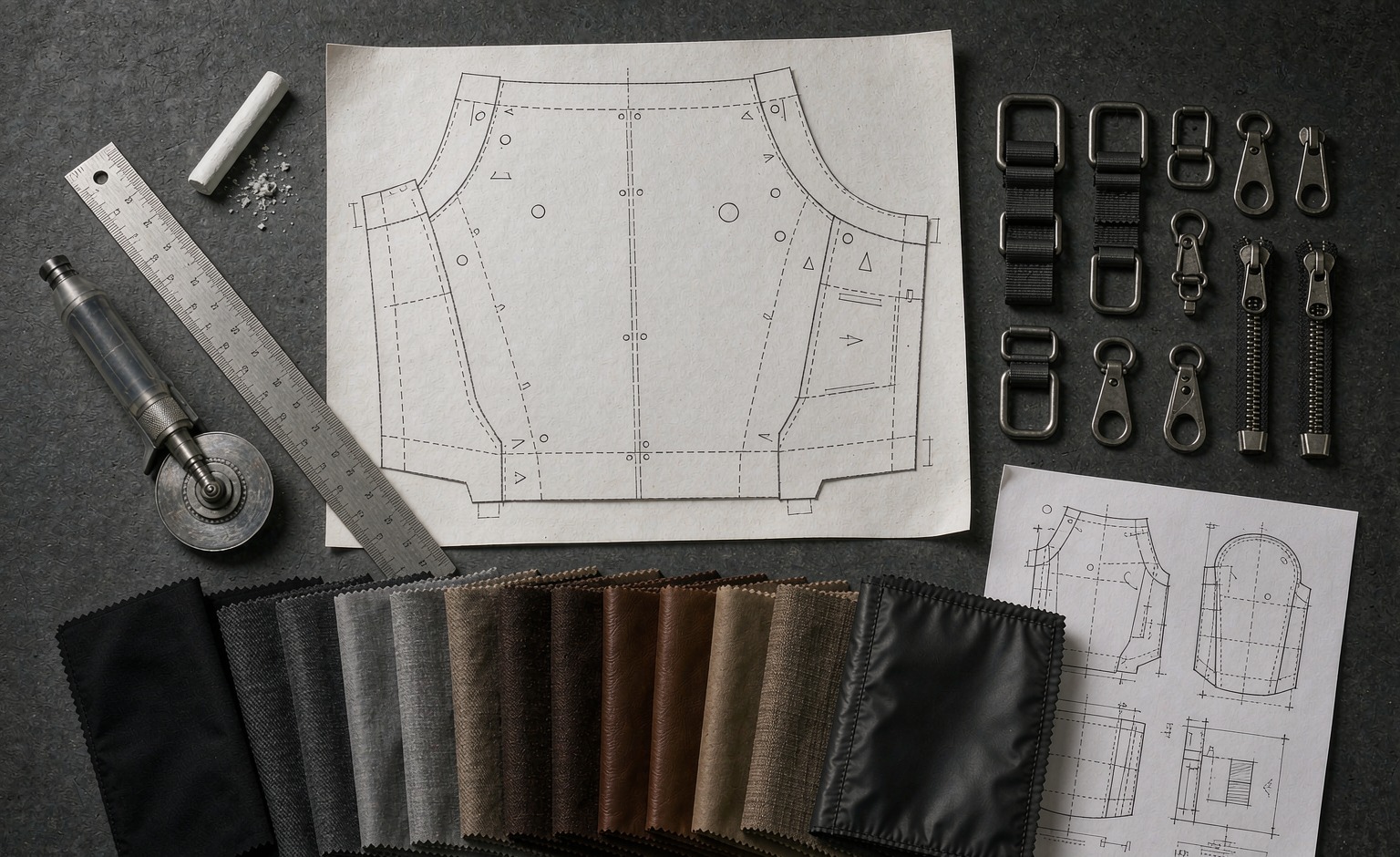
A load path in bag engineering is the continuous chain of material that carries force from the point where weight enters the product to the structural member that finally resolves it, and the product fails at the weakest link in that chain. The route on a modular panel runs from a mounting point at 25 mm webbing through stitch islands pitched 38 mm apart on a 50 mm repeat, into a backing layer, and onward to a structural seam. Designing the path means deciding the entry geometry, the transfer members, the reinforcement placement and the termination, then confirming each with a measured value. Development starts at 500 pieces, samples return in 6-10 working days, volume completes over 35-50 days, and release is held at AQL 2.5. The analysis covers civilian carriage of instrument cases, cable reels, trauma kits, water bottles and handheld devices, and excludes weapons, munitions, armour plate and any defence-standard conformity statement.
What engineers mean when they say a load path
Force does not disappear inside a product. It enters at a point, travels through material, and ends somewhere that can resist it. The load path is that route, drawn as a chain of stages where each stage hands force to the next. A bag with a well-defined path distributes weight into its frame, its harness and its shell in predictable proportions. A bag with an undefined path leaves force to find its own way, and force always finds the shortest route through the weakest material available.
Four stages appear in every bag. Entry is where weight is applied: a handle held in a hand, a shoulder strap over a trapezius, a pouch hanging on a panel, a compression strap pulling against contents. Transfer is the material that carries force away from the entry: webbing, reinforcement tape, a backing panel, a frame sheet. Reinforcement is the local thickening or stiffening placed at points where stress concentrates. Termination is where the force finally resolves, normally a structural seam, a frame member or a spine that closes the body.
The chain is only as strong as its weakest stage, and the useful insight is that strengthening three stages does nothing if the fourth stays weak. A haul loop sewn with excellent webbing, a generous reinforcement patch and beautiful stitching still fails if it terminates into a single thickness of shell fabric instead of a structural seam. That is the most common engineering error in sewn products, and it is invisible from outside.
Drawing the path before sampling is cheap. Mark every entry point on the pattern, trace each route to its termination, and name the material at every stage. Any route that cannot be traced to a structural member is a route that will find its own termination through face fabric.
Selection rule: Trace every entry point on the pattern to a named structural termination before a sample is cut, because a route without a designed termination will terminate in shell fabric and tear there.
Entry points: where weight first enters the structure
Entry geometry governs how concentrated the force is. A handle spreads load across the width of a grip; a single webbing tail concentrates it into the width of the tape. A shoulder harness spreads load across a large area of the back panel; a pouch strap concentrates it into two narrow lines where the strap passes under a row. Concentration is what turns a manageable load into a tear.
Handles deserve specific attention because they are loaded suddenly rather than gradually. A bag lifted by one grab handle applies its full contents mass plus a dynamic factor to a component that may weigh a few grams. The standard remedy is a doubled webbing tail that runs past the grip and terminates into a structural seam rather than into the top panel, plus a box stitch or bar tack at the point where the tail changes direction.
Shoulder strap entry behaves differently. Load here is sustained rather than impact, and the governing concern is creep - slow elongation of foam, webbing and stitch under continuous tension. Creep changes harness geometry over months, which users perceive as the bag sagging. Specifying a low-creep webbing and a strap anchor that terminates into the frame rather than into the back panel is the durable answer.
On a modular face, entry is through the pouch strap into the rows. Because the strap bears upward against the underside of each row, load enters at several points at once, which is why a woven field distributes better than a single-point attachment. Teams building a modular carry platform usually find the panel is not the limiting stage; the termination at the seam behind it is.
Verdict: Classify each entry as impact, sustained or cyclic before choosing reinforcement, because a grab handle needs termination strength while a shoulder anchor needs creep resistance and these call for different materials.
Transfer members: webbing, backing layers and structural seams
Webbing is the primary transfer member in sewn products. It carries tension well, it is cheap, and it terminates cleanly into a seam. Its weakness is at the ends: a webbing tail that stops short of a structural member transfers load into whatever fabric surrounds it, and shell fabric resists tear propagation poorly once a stitch row has perforated it.
Tail length is the single most effective control. A tail that extends 40 mm or more past its last stitch and lands inside a structural seam performs dramatically better than a tail that ends 10 mm past the stitch and stops in face fabric. The extra material costs almost nothing; the difference in field performance is the difference between a bag that survives and a bag that returns.
Backing layers convert a local load into a distributed one. A patch or panel behind an entry point spreads force over a wider area, lowering stress per unit area at every stitch hole. The layer has to be assembled before the entry component is sewn, otherwise the stitches never pass through it and the added material is decorative.
Structural seams are the terminations that matter. A seam that closes the body to the back panel, or that joins the base to the walls, involves multiple plies and a fold, so it resists both shear and peel. A seam that merely joins two pieces of face fabric carries far less. Designers should identify which seams in the pattern are structural and route every load path into one of those.
Bottom line: Extend every webbing tail at least 40 mm past its final stitch and land it inside a multi-ply structural seam, because termination geometry governs field performance more than webbing strength does.
Reinforcement placement: why a patch moves the failure point instead of removing it
Reinforcement is widely misunderstood as a way of making a joint stronger without limit. It does strengthen the reinforced zone, but it also creates a stiffness discontinuity at the patch boundary, and stress concentrates at that boundary. The joint then fails just outside the patch instead of inside it. Nothing has been gained unless the patch boundary falls in a region where stress is already low.
This is why reinforcement shape matters more than reinforcement area. A rectangular patch with square corners creates four stress concentrators. A patch with generously radiused corners, or one that tapers in stiffness through an intermediate layer, spreads the transition. A patch that extends well past the loaded zone pushes its boundary into low-stress territory where the discontinuity no longer matters.
Stitch pattern interacts with patch geometry. A dense stitch block is stiff and creates a hard boundary; a bar tack is short, localised and comparatively forgiving. Box stitch with a diagonal spreads load across a wider area and is often the better choice where entry load is spread across a handle width rather than concentrated in a tape.
The practical rule is to design reinforcement outward from the termination rather than inward from the symptom. Decide where the force should end, build the route to get there, then reinforce the stages along that route. Reinforcing at the tear location after a sample fails is the reverse process and usually produces a second failure a few centimetres away.
Takeaway: Size reinforcement so its boundary sits in a low-stress region and radius every corner, because a patch that ends where stress is still high simply relocates the tear to the patch edge.
The four origins where bags actually start to fail
Field returns cluster around four origins with striking consistency. Recognising them from the damage pattern is faster than any test, and it points directly at the stage that needs redesign.
The first origin is the stitch hole line. A row of perforations through shell fabric is a perforated tear line; when load pulls across it, the fabric tears from hole to hole. This appears as a straight tear following a stitch line, with intact thread and torn cloth. The fix is to put a backing layer behind the line so load transfers into the layer rather than into the perforated cloth.
The second origin is webbing pull-out, where the tail tears free of its stitch block. The damage shows a clean tape end with the stitch block intact and the surrounding fabric torn. The fix is tail length and termination into a structural seam.
The third origin is seam run-out at a panel edge, where a loaded seam simply continues past its last effective stitch and splits. It appears as a peel opening that grows from the edge inward, and it is fixed by extending the seam or adding a termination bar at the end of the run.
The fourth origin is delamination of a coating or laminate from its substrate. The cloth is intact, the stitching is intact, and the coating has lifted, leaving the assembly with no shear transfer. It appears as bubbling or a silvery lift line near a loaded stitch row, and it is fixed at material selection rather than at construction.
| Observed damage | Stage at fault | Mechanism | Redesign action | Verification |
|---|---|---|---|---|
| Straight tear following a stitch line, thread intact | Transfer into shell fabric | Perforation line acting as a tear starter | Add backing layer behind the stitch line | Cut-section check of the stack |
| Clean tape end, stitch block intact, cloth torn around it | Termination of webbing tail | Pull-out because tail ended in face fabric | Extend tail past 40 mm into a structural seam | Pull test on the terminated tail |
| Peel opening growing inward from a panel edge | Seam run-out at the edge | Loaded seam continued past its last effective stitch | Extend seam, add end termination bar | Peel inspection after load cycling |
| Bubbling or silver lift line near a loaded row | Coating or laminate bond | Delamination removing shear transfer | Change substrate or coating system | Bond strength check on the finished panel |
| Elongated slot or widened tape channel | Entry geometry wear | Cyclic threading abrading the entry | Change face family or add edge binding | Cycle test with the intended strap |
Reading the table as a diagnostic: identify the row that matches the physical evidence, then apply the redesign action in the fourth column rather than the intuitive response. The intuitive response to a tear near a stitch line is usually more stitches, which adds more perforations to an already perforated line.
Judgement: Diagnose from the tear pattern first and resist adding stitch density to a perforation-line tear, because extra needle holes weaken the very line that is already tearing.
Reinforcement families compared for stiffness, concentration and edge behaviour
Once the route is known, the reinforcement family is chosen on three criteria: how much stiffness it adds, how sharply its boundary concentrates stress, and how it behaves at the edge of the loaded zone. No family wins all three, which is why a single bag often uses two or three in different places.
| Family | Stiffness added | Boundary concentration | Edge behaviour | Typical placement | Limitation |
|---|---|---|---|---|---|
| Bar tack | Low, very local | Low; short length limits the discontinuity | Forgiving; no hard perimeter | Webbing ends, strap anchors, row islands | Covers little area on its own |
| Box stitch with diagonal | Medium across a defined area | Moderate at the rectangle corners | Fair; radiused corners help | Handle tails, harness anchors | Corner concentration if drawn square |
| Full backing patch | High over a wide area | High at the patch perimeter | Poor unless perimeter is graded | Behind panel fields, behind anchor sets | Moves failure to the patch boundary |
| Sandwiched stiffener plate | Very high, directional | Very high at plate edges | Poor; needs tapering or a soft transition | Back panel, base, frame sheet junction | Adds mass and thickness |
| Riveted or washered fixing | Local, very high | Extreme at the fixing perimeter | Poor; punch-out risk | Base corners, strap ends on stiff shells | Requires sufficient substrate thickness |
The pattern across the table is that stiffness and concentration rise together. Every family that adds substantial stiffness creates a boundary that must be designed, tapered or moved into low-stress territory. The families that are forgiving at the edge are the ones that add little stiffness, which is why they are used repeatedly across an area rather than once.
Combination is the normal answer. A bar tack at each webbing end inside a box stitch, sitting on a backing patch that extends well past both, puts the hard boundary in a region where stress has already fallen. That three-level arrangement appears in most durable bags and is the reason they survive loads that destroy superficially similar products.
Writing a load path into the specification document
Design intent survives only if it is written down in a form the line can follow and the inspector can check. Four lines convert a load path into enforceable requirements, and each needs a number.
- Entry geometry: state the component width, its material and the number of engagement points, for example 25 mm tape engaging a minimum of three rows.
- Transfer member: state the webbing specification, the tail length past the last stitch, and the backing layer construction behind it.
- Reinforcement: state the family, the stitch count, the coverage area and the extension past the loaded zone.
- Termination: name the structural seam or member the route ends in, and state the minimum ply count at that point.
Each line should carry an acceptance method. Tail length and stitch count are dimensional and checked on a sacrificed sample. Termination ply count is checked by cut-section. Overall behaviour is checked by a pull test on the assembled component, reported against a named method such as ASTM D5034 for tensile behaviour of the tape and seam combination, with abrasion resistance referenced to ISO 12947 where the face fabric is also load-bearing.
Programmes that mount heavy kits on a work-grade modular shell should also specify a creep check, because sustained load changes harness geometry over months even where nothing tears. A short sustained-load hang with a measurement before and after is sufficient and costs nothing in sampling time. The same four stages govern structured carry bodies and lighter trail-oriented modular formats, where entry geometry differs but the chain does not.
Spec rule: Require tail length, stitch count, backing construction and named termination seam to appear as separate numbered lines with individual acceptance methods, because a single combined line cannot be inspected.
Programme mechanics: from drawn path to released volume
On the production side, the path above becomes an operation routing that fixes assembly sequence, and sequence decides whether reinforcement actually receives load. Insert backing after field stitching and the finished item looks identical while performing far worse, so the routing is a controlled document rather than a production aid.
Our production team moves through specification, sample, approval, bulk, inspection and shipment in that order. Samples return in 6-10 working days on conventional builds, or 12-15 when a moulding, plating bath or welded feature is new; volume then occupies 35-50 days. Programme coordination is handled by QUANZHOU JUNYUAN BAGS, established 2014, whose founder has been in bag production since 2004.
Capacity: a 4,950 m² SGS-verified production floor carrying 7 production lines and 149 machines, staffed by 137 people, with monthly output near 200,000 units. One reference opens at 500 pieces; development costs USD 50-150, credited against volume, plus USD 300-2,500 for tooling or screens. Terms run FOB Xiamen for guidance, T/T 30/70, with quotations returned inside 24-48 hours.
Release is held at AQL 2.5 under ISO 2859-1 level II - Critical 0, Major 2.5, Minor 4.0 - and path checks such as tail length on sacrificed units, stitch count at reinforcement and ply count at termination are added to the standard inspection so structural intent is sampled rather than assumed. Freight then takes 25-35 days by sea, 5-8 by air or 3-5 by express courier, with planning from 20GP near 28 CBM up to 40HQ near 68 CBM.
What a load path analysis does not predict
A path analysis addresses static and cyclic mechanical load. It says nothing about ultraviolet degradation, which weakens most technical fabrics long before any seam is mechanically challenged, and nothing about hydrolysis of coatings in humid storage. Both are material-ageing questions that require their own testing, typically alongside ISO 12947 abrasion data and a separate exposure programme.
It says nothing about abuse. A bag dragged across a worksite floor, overfilled past its designed volume, or lifted by a component never intended for lifting fails outside any analysis. Designed load ceilings should be stated in the product documentation, and the analysis assumes they are respected.
It says nothing about chemical compliance. Restricted substances are governed separately by REACH (EC 1907/2006) and, for the Californian market, by Prop 65, and those declarations travel with the material set rather than with the mechanical design.
Finally, the scope remains civilian. Load paths are described for instrument cases, cable reels, trauma kits, water bottles and handheld devices. No weapon carriage, munitions storage or armour plate is addressed, and no defence-standard conformity is implied or claimed anywhere in this treatment.
Frequently asked questions
What is a load path in bag engineering?
The continuous chain of material carrying force from where weight enters to the structural member that resolves it. Four stages appear every time: entry, transfer, reinforcement and termination. The bag fails at the weakest stage, so all four appear in the specification. Programmes open at MOQ 500 with sampling across 6-10 working days.
Why does adding a reinforcement patch sometimes move the failure instead of fixing it?
A patch stiffens its own area and creates a stiffness discontinuity at its boundary, so stress concentrates there. Unless the boundary sits in a low-stress region, the tear relocates to the patch edge. Extend the patch well past the loaded zone and radius every corner.
How long should a webbing tail extend past its last stitch?
At least 40 mm, landing inside a multi-ply structural seam rather than stopping in face fabric. Tail length and termination geometry govern field performance more than webbing strength, and the extra material costs almost nothing per unit.
- Extend past 40 mm
- Land in a structural seam
- Back the stitch line
- Record ply count
What are the four stages every load path contains?
Entry where weight is applied, transfer through webbing and backing, reinforcement at stress concentrations, and termination into a structural seam or frame member. Trace each entry to a named termination on the pattern before any sample is cut.
Which failure origin is most common in returned bags?
Tears following a stitch line, because needle holes form a perforation line through shell fabric. The thread stays intact and the cloth tears hole to hole. Add a backing layer behind the line rather than increasing stitch density.
How can the responsible stage be identified from a tear pattern?
Match the evidence: a straight tear along stitches indicates transfer into shell fabric, a clean tape end with intact stitching indicates pull-out, an edge peel indicates seam run-out, and bubbling near a row indicates coating delamination. Each maps to a different redesign action.
Why do grab handles fail more often than shoulder anchors?
Handles carry impact load rather than sustained load, applying full contents mass plus a dynamic factor through a small component. Shoulder anchors fail by creep instead, slowly changing harness geometry over months of continuous tension.
What reinforcement family suits a webbing end?
A bar tack, because it adds little stiffness and therefore little boundary concentration. Pair it with a box stitch and a backing patch extending well past both, which places the hard boundary where stress has already fallen.
Does stiffness always improve a load path?
No. Stiffness and boundary concentration rise together, so every stiff element creates an edge that must be designed, tapered or moved into low-stress territory. Families that are forgiving at the edge add comparatively little stiffness.
Which test methods support a load path specification?
Tensile behaviour of the tape and seam combination is reported against ASTM D5034, abrasion resistance of load-bearing face fabric against ISO 12947, and release sampling follows ISO 2859-1 at level II. Naming the method makes two quotations comparable.
How is termination ply count verified on a finished bag?
By cut-section on a sacrificed unit. Sampling occupies 6-10 working days, and one sacrificed sample per reference is enough to confirm that the route ends in a multi-ply structural seam rather than in face fabric.
What should a load path specification contain as separate lines?
Entry geometry, transfer member with tail length and backing construction, reinforcement family with stitch count and coverage, and the named termination seam with minimum ply count. Each needs its own acceptance method to be inspectable.
- Entry
- Transfer
- Reinforcement
- Termination
How long does bulk production take once a path is approved?
Volume occupies 35-50 days once samples are approved, after 6-10 working days of development, or 12-15 where moulding or plating is new. Release inspection then runs at AQL 2.5 under ISO 2859-1 level II.
What does a first reference cost besides unit price?
Development is billed at USD 50-150 and credited against the volume order, plus USD 300-2,500 for tooling or screens where hardware is new. A reference opens at 500 pieces, quoted for guidance FOB Xiamen, settled T/T 30/70, answered in 24-48 hours.
Does load path analysis predict ultraviolet or chemical ageing?
No. It addresses mechanical load only. Sunlight ageing, coating hydrolysis in humid storage and restricted-substance screening under REACH (EC 1907/2006) need their own material tests and their own supplier declarations.
What scope is excluded from this load path treatment?
Weapons, munitions, armour plate and defence-standard conformity all sit outside it. Included instead are instrument cases, cable reels, trauma kits, water bottles and handheld devices carried by licensed civilian operators.